
Interspinous process device and method

a process device and interspinous technology, applied in the field of spine, can solve the problems of reducing the disc space height, and reducing the foramenal height of the vertebrae, so as to achieve the effect of increasing the distance and reducing the distan

Active Publication Date: 2010-11-04
NUVASIVE SPECIALIZED ORTHOPEDICS INC
View PDF44 Cites 73 Cited by
  • Summary
  • Abstract
  • Description
  • Claims
  • Application Information

AI Technical Summary

Benefits of technology

The invention is a device that can be used to adjust the distance between adjacent spinous processes in a spine without needing additional surgeries. It consists of a housing that is attached to the first spinal process and a magnetic assembly that is attached to the second spinal process. The magnetic assembly has a hollow magnet that can be rotated using an external magnetic field to adjust the distance between the spinous processes. The device can be adjusted by rotating the hollow magnet in one direction or the other, which causes the magnetic assembly to elongate or shorten. This allows for non-invasive adjustment of the spine without needing additional surgeries.

Problems solved by technology

This can result in a decrease in the disc space height.
In addition, the facets and ligaments of the spine degenerate as well over time.
These problems can lead to a reduction in the foramenal height of the vertebrae.
Because the nerves pass through the respective foramen, a reduction in the foramenal height may often causes nerve tissue to get pinched leading to various types of back pain.
These pinched or compressed nerves can also lead to difficulty in walking.
Often, these devices are successful in alleviating symptoms of patients post surgery, however, many patients have recurring symptoms after months or years have passed.

Method used


Image

  • Interspinous process device and method
  • Interspinous process device and method
  • Interspinous process device and method

Examples


Embodiment Construction

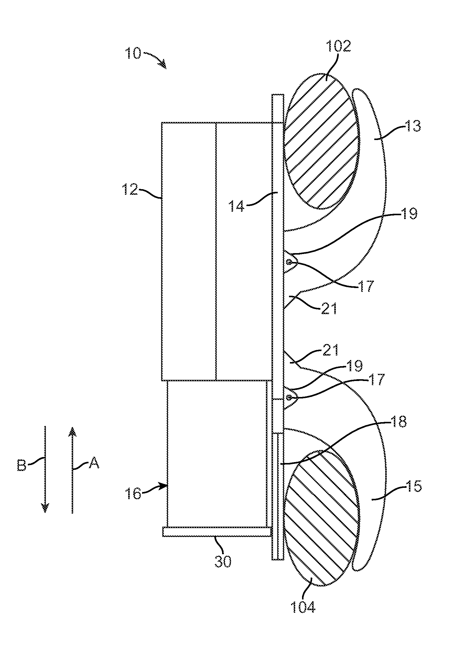
[0022]FIGS. 1A, 1B, and 1B illustrate an interspinous process device 10 according to one embodiment. The interspinous process device 10 is configured to mount on a subject's spine 100 as illustrated in FIG. 3. For example, the interspinous process device 10 is mounted between adjacent spinous processes 102, 104. The interspinous process device 10 is configured to adjust its length in a non-invasive manner. As explained herein in more detail, an external adjustment device 1130 (FIGS. 4, 5, 6, 7A-7D, and 8) is provided that can lengthen or shorten the interspinous process device 10 on an as needed basis. The interspinous process device 10 includes a housing 12 that is affixed or otherwise coupled to a first mounting surface 14. The housing 12 may be made of any biocompatible, non-magnetic material such as, for instance, stainless steel, titanium or the like. A moveable magnetic assembly 16 is telescopically disposed within the housing 12. The magnetic assembly 16 is moveable in the di...


PUM


Abstract

An interspinous process device is configured for placement between adjacent spinous processes on a subject's spine. The device includes a housing configured for mounting to a first spinal process, the housing having a lead screw fixedly secured at one end thereof. A magnetic assembly is at least partially disposed within the housing and configured for mounting to a second spinal process. The magnetic assembly includes a hollow magnet configured for rotation within the magnetic assembly, the hollow magnet comprising a threaded insert configured to engage with the lead screw. An externally applied magnetic field rotates the hollow magnet in a first direction or a second, opposite direction. Rotation of the hollow magnet in the first direction causes telescopic movement of the magnetic assembly out of the housing (i.e., elongation) and rotation in the second direction causes telescopic movement of the magnetic assembly into the housing (i.e., shortening).

Description

REFERENCE TO RELATED APPLICATIONS[0001]This Application claims priority to U.S. Provisional Patent Application No. 61 / 173,902 filed on Apr. 29, 2009. U.S. Provisional Patent Application No. 61 / 173,902 is incorporated by reference as if set forth fully herein.FIELD OF THE INVENTION[0002]The field of the invention generally relates to medical devices for treating disorders of the skeletal system and in particular the spinal system.BACKGROUND OF THE INVENTION[0003]As individuals age, their spinal discs tend to degenerate over time. This can result in a decrease in the disc space height. In addition, the facets and ligaments of the spine degenerate as well over time. These problems can lead to a reduction in the foramenal height of the vertebrae. The foramen is a natural opening between the vertebrae that allows the passage of respective nerves from the spinal cord. Because the nerves pass through the respective foramen, a reduction in the foramenal height may often causes nerve tissue ...

Claims


Application Information

Patent Timeline
Patent Type & Authority Applications(United States)
IPC IPC(8): A61B17/70
CPCA61B17/7065A61B17/7056A61B17/7068A61B2017/00022A61B2017/00039A61B2017/00411A61B2017/00876
Inventor POOL, SCOTTCHANG, ARVINTRAN, PETER P.WALKER, BLAIR
Owner NUVASIVE SPECIALIZED ORTHOPEDICS INC
Learn More