
Dc-dc converter

a converter and dc-dc technology, applied in the direction of engine-driven generators, battery/fuel cell control arrangements, transportation and packaging, etc., can solve the problems of reducing the effective capacity wasting space in the installation of the alternator, and reducing the internal physicochemical property so as to prevent the increase in space and cost, determine the effective capacity or characteristic degradation state of the secondary battery, and effectively use a dc-d

Inactive Publication Date: 2010-11-04
MURATA MFG CO LTD
View PDF3 Cites 28 Cited by
  • Summary
  • Abstract
  • Description
  • Claims
  • Application Information

AI Technical Summary

Benefits of technology

[0015]It is possible to determine the effective capacity or characteristic degradation state of a secondary battery with the above-described DC-DC converter required for charging of the secondary battery without using another dedicated circuit.
[0017]A preferred embodiment of the DC-DC converter may further include an alerting device arranged to notify, when the characteristic evaluating unit detects that the secondary battery reaches an end of its useful life, a user of a result of the detection. As a result, it is possible to replace the secondary battery at an appropriate time and therefore prevent the problem of battery exhaustion.
[0018]A switching element to be turned off at the time of evaluation performed by the characteristic evaluating unit may preferably be connected in series to the capacitor. As a result, it is possible to prevent the resonance operation of the inductor or the inductance component of a line and the capacitor and therefore prevent the application of an overvoltage to the rectifier-side synchronous rectifier element or the commutator-side synchronous rectifier element.
[0021]The characteristic evaluating unit determines the effective capacity or characteristic degradation state of the secondary battery within a predetermined period of time, for example, before a converter operation is started. As a result, since evaluation processing can be performed before the charging of the secondary battery is started, it is possible to more accurately determine the effective capacity or characteristic degradation state of the secondary battery. Furthermore, since the original function of a DC-DC converter of charging a secondary battery is not inhibited, the charging performance of a secondary battery is not reduced.
[0024]According to a preferred embodiment of the present invention, it is possible to determine the effective capacity or characteristic degradation state of a secondary battery without using a special dedicated circuit by effectively using a DC-DC converter required for charging of the secondary battery. This can prevent the increase in space and cost and a problem caused by the decrease in the effective capacity of a secondary battery.

Problems solved by technology

Repeated charging / discharging of secondary batteries degrades the internal physicochemical property of the secondary batteries and reduces the effective capacity of the secondary batteries.
In the case of hybrid vehicles, an electric motor is installed in advance and the installation of an alternator is therefore a waste of space.
However, when “battery exhaustion” of a lead-acid battery occurs, like gasoline-driven vehicles, hybrid vehicles cannot move.
Even if a lithium-ion battery tries to start a gasoline engine, it is impossible to start the gasoline engine because a DC-DC converter does not have a current capacity required for driving of a starter motor.
This requires space and cost.

Method used


Image

  • Dc-dc converter
  • Dc-dc converter
  • Dc-dc converter

Examples


first preferred embodiment

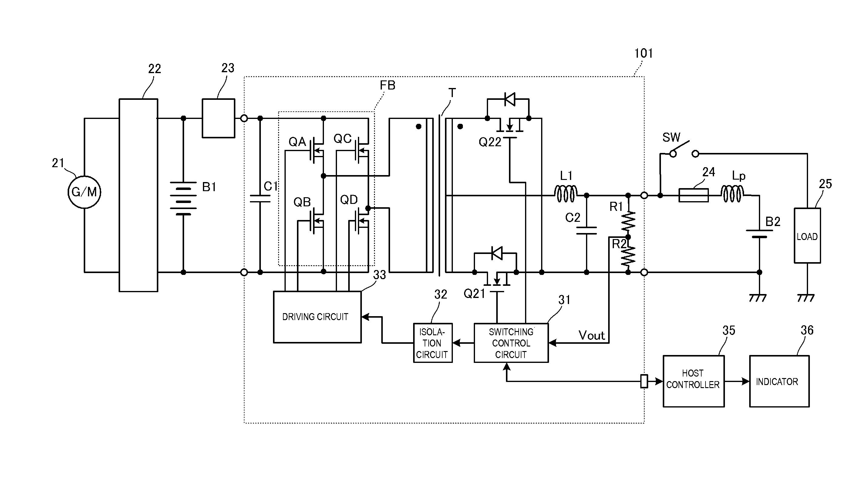
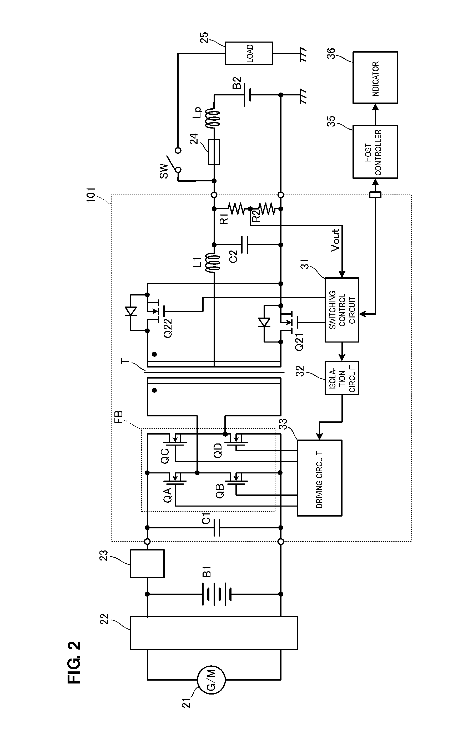
[0034]FIG. 2 is a circuit diagram illustrating the circuit configuration of a DC-DC converter according to the first preferred embodiment of the present invention and a peripheral circuit. The illustrated circuit is a charging / discharging circuit for a hybrid vehicle, and includes the electric motor (generator) 21, a first secondary battery B1, and a second secondary battery B2.

[0035]The electric motor 21 functions as a generator while a hybrid vehicle travels with a gasoline engine, and functions as an electric motor while the hybrid vehicle is driven by a lithium-ion battery.

[0036]A charging / discharging control circuit 22 is disposed between the electric motor (generator) 21 and the first secondary battery B1. A switching circuit 23 is disposed between the first secondary battery B1 and the input portion of a DC-DC converter 101. The output portion of the DC-DC converter 101 is connected to the second secondary battery B2 via a fuse 24. An inductance of a line between the output p...

second preferred embodiment

[0058]FIG. 6 is a circuit diagram illustrating the circuit configuration of a DC-DC converter according to the second preferred embodiment and a peripheral circuit. A DC-DC converter 102 according to the second preferred embodiment differs from the DC-DC converter 101 according to the first preferred embodiment illustrated in FIG. 2 in that a switching element Q3 is connected in series to the capacitor C2. The switching control circuit 31 is turned off only when the characteristic evaluation of the second secondary battery B2 is performed, and is in the ON state at the time of the normal driving. Except for the switching element Q3, the configuration of the DC-DC converter 102 is the same as that illustrated in FIG. 2.

[0059]Thus, by blocking the path of a current passing through the capacitor C2 using the switching element Q3 only at the time of the characteristic evaluation, the LC resonance operation of the inductor L1 or the parasitic inductor Lp and the capacitor C2 is prohibite...

third preferred embodiment

[0060]Exemplary isolated DC-DC converters have been described in the first and second preferred embodiments. In the third preferred embodiment, an exemplary non-isolated DC-DC converter will be described. FIG. 7 is a circuit diagram illustrating the circuit configuration of a DC-DC converter according to the third preferred embodiment and a peripheral circuit. The configuration illustrated in FIG. 7 is the same as that described in the first and second preferred embodiments except for a DC-DC converter 103. The DC-DC converter 103 includes a rectifier-side synchronous rectifier element Q11, a commutator-side synchronous rectifier element Q12, the inductor L1, and the capacitor C2 which define a synchronous rectification circuit. The DC-DC converter 103 includes the smoothing capacitor C1 on the side of the input portion thereof and an output voltage detection circuit including the resistors R1 and R2 on the side of the output portion thereof.

[0061]A switching control circuit 41 perf...


PUM


Abstract

A DC-DC converter includes an inductor, a capacitor, an output voltage detection circuit, and a synchronous rectification circuit including a rectifier-side synchronous rectifier element and a commutator-side synchronous rectifier element. The commutator-side synchronous rectifier element is turned on so as to pass a current through a closed loop composed of the commutator-side synchronous rectifier element, the inductor, and a second secondary battery. The characteristic evaluation of the second secondary battery is performed on the basis of the decrease in a detection voltage Vout of an output voltage Vo. As a result, it is possible to determine the effective capacity or characteristic degradation state of the second secondary battery with a circuit to charge the second secondary battery without using a dedicated circuit.

Description

BACKGROUND OF THE INVENTION[0001]1. Field of the Invention[0002]The present invention relates to a DC-DC converter preferably for use in, for example, hybrid vehicles, and that is capable of determining a effective capacity or characteristic degradation state of a 12V lead-acid battery that is the same as that used in gasoline-driven vehicles in the related art.[0003]2. Description of the Related Art[0004]Repeated charging / discharging of secondary batteries degrades the internal physicochemical property of the secondary batteries and reduces the effective capacity of the secondary batteries. When the effective capacity of such a secondary battery decreases to a certain level, it is determined that the secondary battery reaches the end of its useful life. It is necessary to replace the secondary battery.[0005]In order to prevent the full discharging of a lead-acid battery, that is, “battery exhaustion” in vehicles for starting an engine with a starter motor, it is important that the ...

Claims


Application Information

Patent Timeline
Patent Type & Authority Applications(United States)
IPC IPC(8): H02J7/10
CPCB60L11/1864B60L2210/10H02J7/0054H02J7/1423H02J2007/0059H02M3/33592Y02T10/70Y02T10/7016Y02T10/7061Y02T10/7216Y02T10/92B60L11/14Y02T10/7077Y02T10/7005B60L50/16B60L58/21H02J7/342H02J2207/20Y02T10/7072Y02T10/72
Inventor HARA, TAKASHINISHIYAMA, TAKAYOSHIUEKI, KOICHI
Owner MURATA MFG CO LTD
Learn More