
Radial tire for aircraft

a technology for aircraft and tires, applied in aircrafts, special tyres, transportation and packaging, etc., can solve problems such as increasing tire weight, and achieve the effects of reducing stiffness, reducing elongation, and reducing the performance of the cord

Inactive Publication Date: 2010-11-04
BRIDGESTONE CORP
View PDF7 Cites 5 Cited by
  • Summary
  • Abstract
  • Description
  • Claims
  • Application Information

AI Technical Summary

Benefits of technology

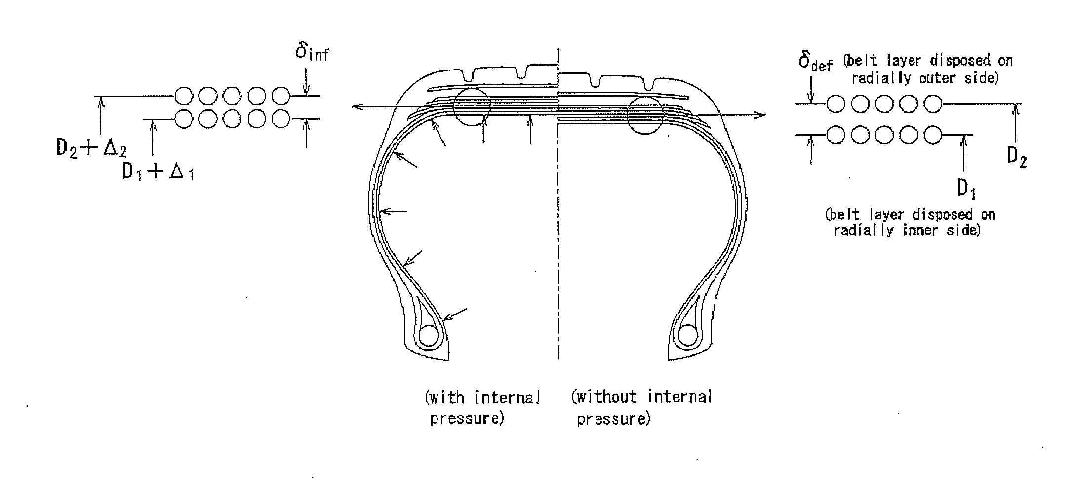
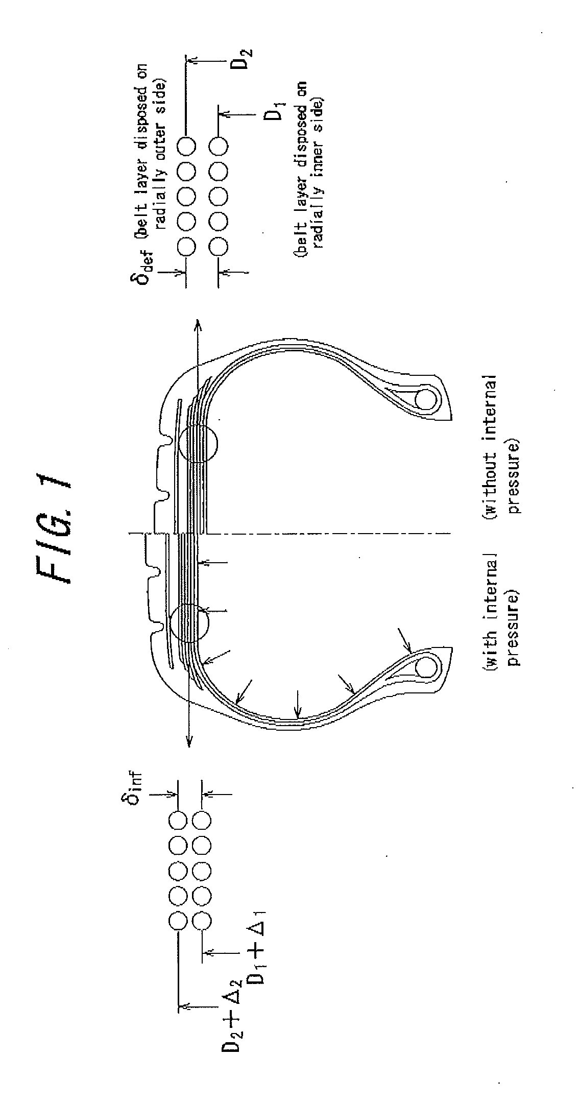
[0046]It is noted that the structure and the layer number of the belt shown in the widthwise sectional view of a tire of FIG. 3 are not particularly limited but can be appropriately adjusted as long as the advantageous effects of the present invention can be obtained.
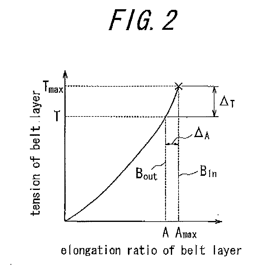
[0047]It is preferable that elongation at break lin of the organic fiber cords constituting the radially innermost belt layer and elongation at break lout of the organic fiber cords constituting the radially outermost belt layer satisfy the relationship 0.8<lout / lin<0.95. That is to say, in order to further obtain the advantageous effects of the present invention by adjusting elongation at break of the organic fiber cords constituting the radially innermost belt layer and the radially outermost belt layer, it is preferable that the ratio lout / lin is in a range of 0.8<lout / lin<0.95.
[0048]In case that the belt is formed by layering at least two belt layers consisting of plies having a plurality of organic fiber cords coated with rubber in such a manner that the organic fiber cords intersect with each other between the belt layers, it is preferable that an inclination angle with respect to the tire equatorial plane of the organic fiber cords constituting a radially outer belt layer is not more than an inclination angle with respect to the tire equatorial plane of the organic fiber cords constituting a radially inner belt layer between respective radially adjacent belt layers.
[0049]That is to say, by making an inclination angle with respect to the tire equatorial plane of the organic fiber cords constituting a radially outer belt layer be not more than an inclination angle with respect to the tire equatorial plane of the organic fiber cords constituting a radially inner belt layer, it is possible to reduce elongation at break in tire circumferential direction from a radially inner belt layer to a radially outer belt layer and to break the organic fiber cords constituting the radially inner and outer belt layers at the same time when the tire is broken by high internal pressure. In other words, performance of the cords can be further utilized.
[0050]It is preferable that an inclination angle with respect to the tire equatorial plane of the organic fiber cords is within a range between 0 degrees and 45 degrees. If the angle exceeds 45 degrees, the belt relatively reduces its stiffness in the circumferential direction and cannot sufficiently function as a member supporting water pressure in the water pressure test to be described below.
[0051]It is preferable that the number of twist turns of the organic fiber cords constituting a radially outer belt layer is not more than the number of twist turns of the organic fiber cords constituting a radially inner belt layer between respective radially adjacent belt layers. In general, as shown in FIG. 5, when the number of twist turns of cords is decreased (C3>C2>C1), as elongation at break of cords is decreased (A3>A2>A1), tension of cords tends to be increased (T3<T2<T1). That is to say, by making a radially outer belt layer have organic fiber cords having the number of twist turns of not more than that of organic fiber cords constituting a radially inner belt layer, cord strength is increased and elongation at break of the radially outermost belt layer can be preferably decreased. It is noted that the above-mentioned number of twist turns means the number of upper twist turns.EXAMPLE

Problems solved by technology

However, even if the number of belt layers is merely increased and pressure resistance is improved for the increase of the number of belt layers, increase in tire weight becomes a problem.

Method used


Image

  • Radial tire for aircraft
  • Radial tire for aircraft
  • Radial tire for aircraft

Examples


example

[0052]Pneumatic tires having a size of 46×17R20-30PR and various specifications shown in Table 1 are produced. Each tire is mounted on a normal rim according to TIRE and RIM Association (TRA) and weight and pressure resistance of each tire are investigated. Pressure resistance of a tire is investigated as a factor of safety (pressure at break). The results are shown in Table 1.

[0053]A zigzag endless belt, as shown in FIG. 6a, formed by spirally winding a strip-shaped ply 8 which is curved in a zigzag manner, multiple times in the circumferential direction and a circumferential spiral belt, as shown in FIG. 6b, formed by spirally winding a strip-shaped ply 8 in the circumferential direction in such a manner that the ply 8 is slightly inclined with respect to the tire equator are used as a belt. The dashed lines in the strip-shaped plies 8 in FIGS. 6a and 6b show cords. In Table 1, A means a zigzag endless belt and B means a circumferential spiral belt.

[0054]Pressure resistance of eac...


PUM


Abstract

The present invention relates to a radial tire for an aircraft having a belt structure capable of sufficiently satisfying a demand for recent high pressure resistance without increase in tire weight and more particularly to a radial tire for an aircraft having a carcass serving as a framework and toroidally extending between a pair of bead portions, and a belt disposed on a radially outer side of the carcass and consisting of at least two belt layers consisting of plies having a plurality of organic fiber cords coated with rubber, wherein the belt is configured in such a manner that elongation at break Lout of a radially outermost belt layer is smaller than elongation at break Lin of a radially innermost belt layer, a ratio Lout / Lin satisfies the relationship 0.8<Lout / Lin<0.95, and elongation at break of a radially outer belt layer is not more than elongation at break of a radially inner belt layer between respective radially adjacent belt layers.

Description

[0001]TECHNICAL FIELD[0002]The present invention relates to a radial tire for an aircraft and more particularly to a radial tire for an aircraft which intends to improve pressure resistance.RELATED ART[0003]High-level demands for safety have been made on a radial tire for an aircraft and it is necessary for a tire to have pressure resistance not less than four times of regular internal pressure.[0004]In order to meet such demands, a radial tire for an aircraft secures its pressure resistance by arranging a carcass serving as a framework and toroidally extending between a pair of bead portions, and a belt on a radially outer side of the carcass and consisting of a plurality of belt layers consisting of plies having a plurality of cords coated with rubber.[0005]As such a radial tire for an aircraft, WO2003 / 061991 discloses a tire capable of restraining radial expansion of the tire without increase in the number of belt layers by using a belt consisting of belt layers having different ...

Claims


Application Information

Patent Timeline
Patent Type & Authority Applications(United States)
IPC IPC(8): B60C9/18B60C9/02
CPCB60C9/2009Y10T152/10801Y10T152/1081B60C2200/02
Inventor YANO, TAKESHI
Owner BRIDGESTONE CORP
Learn More