
Humeral head resurfacing implant and methods of use thereof

a technology of humeral head and implant, which is applied in the field of shoulder replacement, can solve the problems of limiting the load transfer capability between the prosthesis and the humerus, voids between the bone and the implanted prosthesis, and earlier failure tim

Inactive Publication Date: 2010-10-28
GUNTHER STEPHEN B
View PDF87 Cites 38 Cited by
  • Summary
  • Abstract
  • Description
  • Claims
  • Application Information

AI Technical Summary

Benefits of technology

The non-modular design enhances implant strength and fixation, decreases loosening rates, extends wear life, and allows for adequate glenoid exposure, minimizing bone loss and facilitating more complex surgeries like total shoulder replacements while conserving healthy bone.

Problems solved by technology

Because the size and shape of the humerus and humeral head of a patient can vary greatly, due to, e.g., size, gender, bone structure, and disease, matching a properly sized prosthesis to the defect can be difficult, and typically results in the presence of voids between the bone and implanted prosthesis.
These voids result in limited contact between the prosthesis and the reamed bone and may limit the load transfer capability between the prosthesis and the humerus.
Modular humeral head resurfacing implants have been used to overcome these limitations, but modular implants suffer from several limitations, including, e.g., increased wear and tear, which generally results in an earlier failure time, and a reduction in load bearing capabilities.
Furthermore, improper selection, placement, positioning, and fixation of the modular implant components can result in unusual stress conditions causing implant loosening and a subsequent reduction in the service life of the implant.
Periodic, long-term follow-up is needed to monitor the position and state of the implant components, as well as the condition of the adjoining bone, thus causing inconvenience to the patient and a reduced quality of life.
Currently used resurfacing humeral implants are also limited in that they do not allow adequate exposure to the glenoid surface during total shoulder replacement surgeries in cases where both a glenoid implant and a resurfacing humeral implant are needed.

Method used


Image

  • Humeral head resurfacing implant and methods of use thereof
  • Humeral head resurfacing implant and methods of use thereof
  • Humeral head resurfacing implant and methods of use thereof

Examples


example

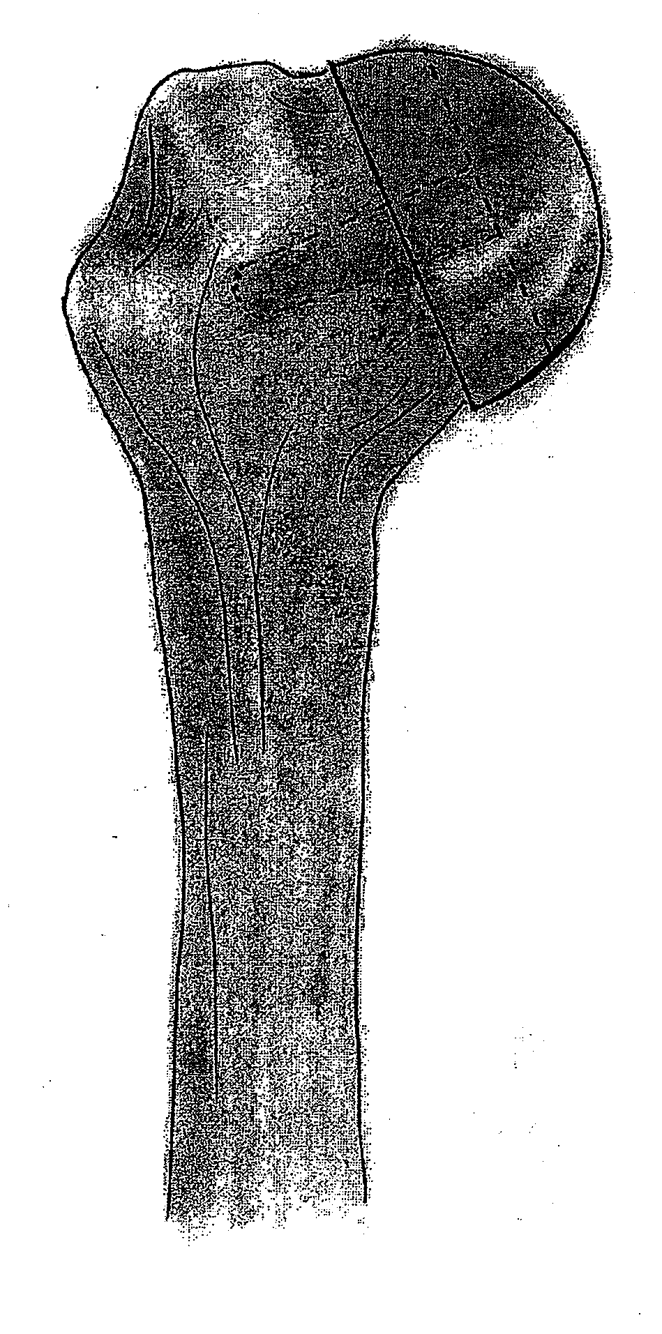
[0042]A middle aged patient presents with shoulder arthritis involving both sides of the shoulder joint (glenoid and humeral head). Because the patient is relatively young (45-65 years old), one goal of the surgery would be to conserve as much of the patient's bone as possible. However, current resurfacing humeral head implants do not allow adequate visualization (exposure) of the glenoid vault in order to implant a glenoid component, and thus, a total shoulder replacement surgery under these circumstances would involve cutting away the entire humeral head in order to provide sufficient exposure to the glenoid. This would result in a significant loss of the patient's humeral bone.

[0043]The non-modular humeral resurfacing implant of the invention would allow the surgeon to save important humeral bone because its use would require resecting only as much of the humeral head as would be required to allow glenoid visualization. Generally, this amount is about 20% to about 50% of the hume...


PUM


Abstract

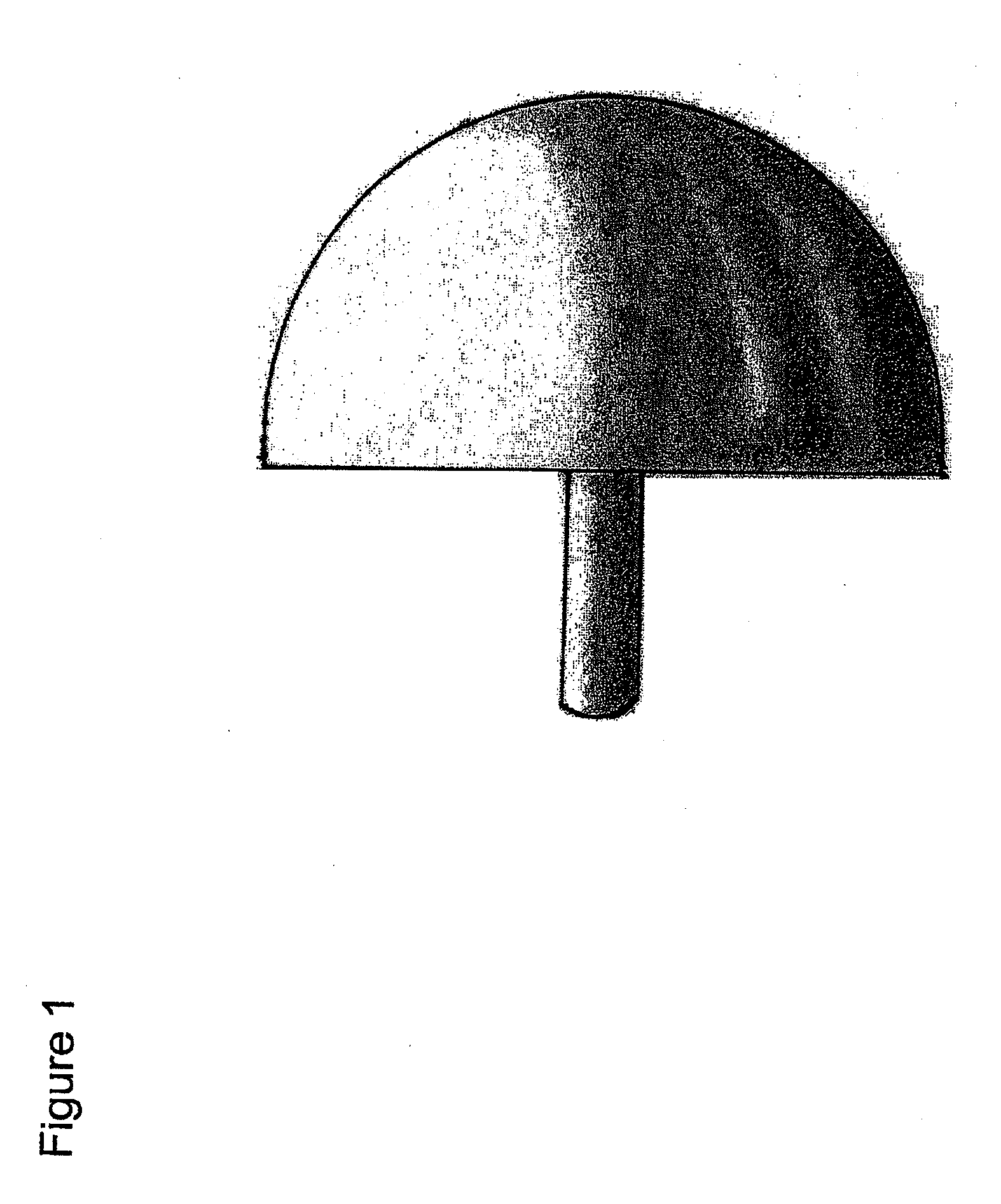
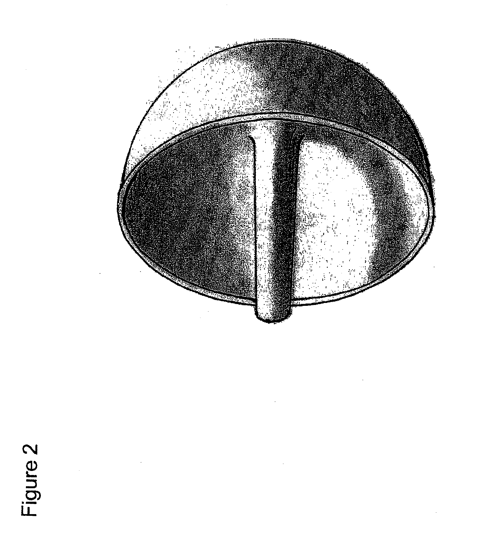
The invention features a monoblock (non-modular) humeral head (shoulder) resurfacing implant designed to replace a portion of the patient's humeral head. The humeral head may need replacing due to trauma, osteonecrosis, infection, arthritis, or other causes. The implant of the invention is designed to be performed either as a hemiarthroplasty or as a component of a total shoulder replacement along with a standard glenoid or inset glenoid implant.

Description

CROSS-REFERENCE TO RELATED APPLICATIONS[0001]This is a continuation application of U.S. patent application Ser. No. 11 / 489,994 filed on Jul. 20, 2006, the entirety of which is hereby incorporated by reference herein and made a part of the present specification.FIELD OF THE INVENTION[0002]The present invention relates to the field of shoulder replacement.BACKGROUND OF THE INVENTION[0003]Shoulder replacement surgery has been an excellent treatment option for patients with disabling pain related to shoulder arthritis. Humeral implants utilized in such replacement surgeries are typically made from metal, and the implants are fixed to the bone either with bone cement (polymethylmethacrylate) or by press fitting the implant to the bone using a roughened inner surface coating on the metal for bony integration. There are two types of humeral head implants in current use: those that replace the humeral head (e.g., implants that include a humeral head and stem that is inserted into a pre-dril...

Claims


Application Information

Patent Timeline
Patent Type & Authority Applications(United States)
IPC IPC(8): A61F2/40
CPCA61B17/15A61F2/4003A61F2002/30253A61F2002/30649A61F2002/4007A61F2002/4631A61F2230/0076A61B2017/1778A61F2002/30878A61B17/1778
Inventor GUNTHER, STEPHEN B.
Owner GUNTHER STEPHEN B
Learn More