
Aneurysm treatment system, device and method

a technology for aneurysms and aneurysms, applied in the field of occlusion systems, can solve the problems of permanent and irreversible occlusion of parent arteries, disadvantages of injection of these types of embolic materials, and a great deal of trauma to patients, and achieve the effect of precise patch orientation

Inactive Publication Date: 2010-10-28
LAKE REGION MFG
View PDF102 Cites 57 Cited by
  • Summary
  • Abstract
  • Description
  • Claims
  • Application Information

AI Technical Summary

Benefits of technology

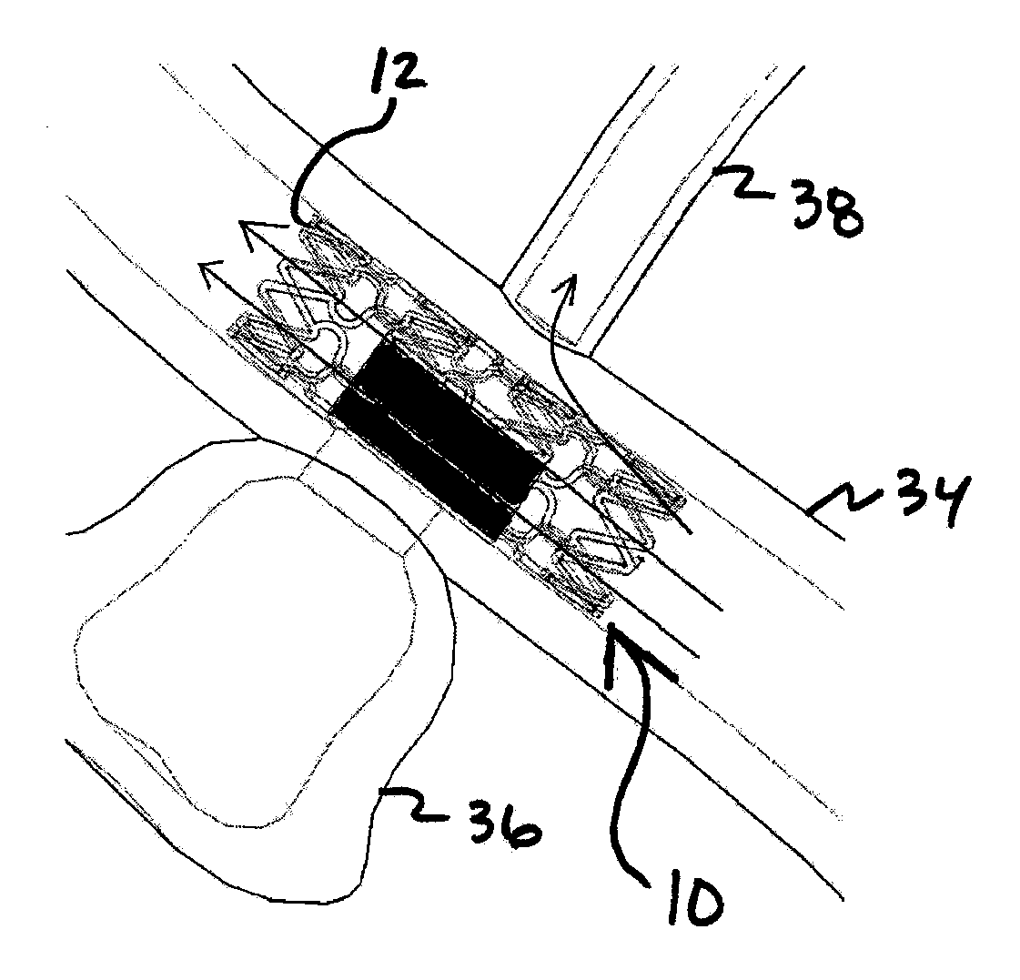
[0005]Briefly in one aspect, the invention includes a cylindrical intravascular aneurysm treatment device. The device includes an expandable sleeve or scaffold having a fluid-flow-restricting portion or patch, where the patch is located on the sleeve so as to inhibit fluid flow through at least part of the sleeve when the sleeve is intravascularly deployed. The device also includes a radiopaque marker, or a plurality of radiopaque markers, disposed on the sleeve, the marker(s) having a defined relationship with respect to the patch such that deployment of the sleeve within the vasculature while observing the marker(s), e.g. by means of a fluoroscope, permits precise orientation of the patch.

Problems solved by technology

Also, the patient undergoes a great deal of trauma in the area of the aneurysm by virtue of the fact that the surgeon must sever various tissues in order to reach the aneurysm.
The injection of these types of embolic materials suffers from disadvantages, most of which are associated with migration of the embolic material out of the aneurysm into the parent artery.
This can cause permanent and irreversible occlusion of the parent artery.

Method used


Image

  • Aneurysm treatment system, device and method
  • Aneurysm treatment system, device and method
  • Aneurysm treatment system, device and method

Examples


Embodiment Construction

and attached Claims. It is understood that some of the Figures are an inventor's visualization of the structures and relationships shown as a combination of a visual impression and what would be seen, e.g. by viewing the device with a fluoroscope. In other words, once the device is intravascularly placed, visual monitoring is no longer possible and the fluoroscopically viewable features, e.g., the markers, are all that can be monitored.

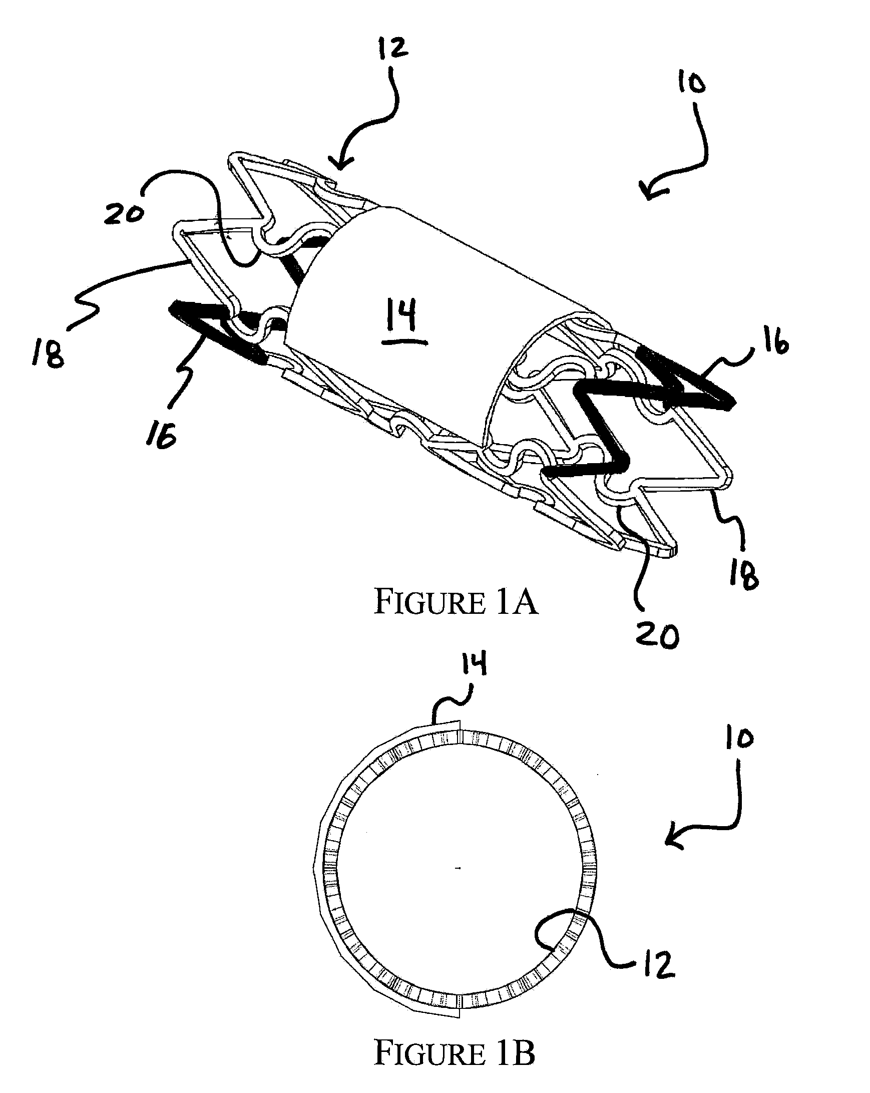
[0012]FIG. 1A is a perspective view of an aneurysm treatment device in accordance with at least one embodiment of the present invention;

[0013]FIG. 1B is a longitudinal end view of the device in FIG. 1A in accordance with at least one embodiment of the present invention;

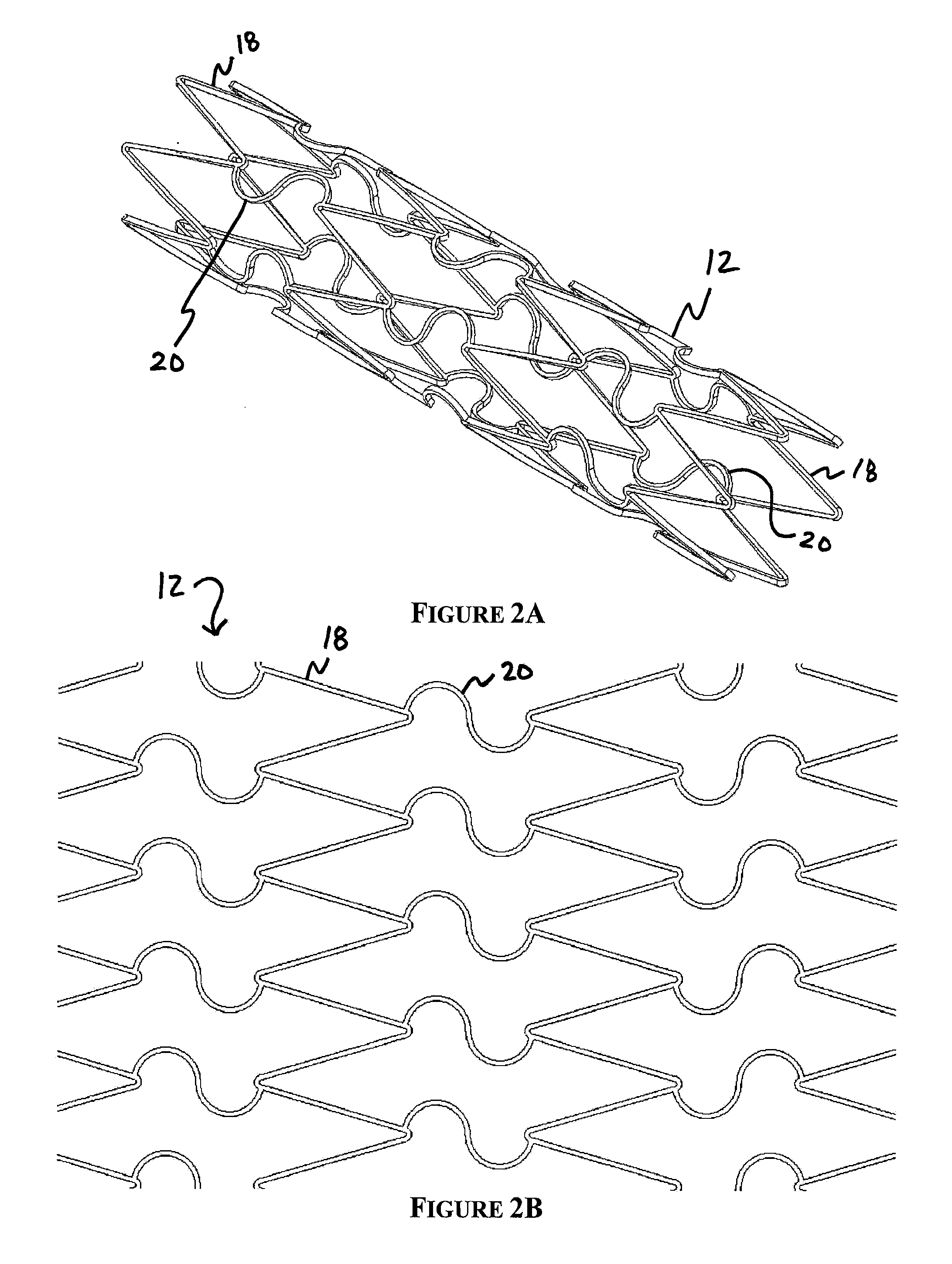
[0014]FIG. 2A is a perspective view of a sleeve-shaped scaffold for use in an aneurysm treatment device in accordance with at least one embodiment of the present invention;

[0015]FIG. 2B is a flat perspective view of the scaffold in FIG. 2A;

[0016]FIG. 3A is a perspective view of an aneur...


PUM


Abstract

An occlusion system, method, and apparatus which treats an aneurysm in a primary vessel such as an intracranial vessel. Aneurysm types treatable by means of this invention include bulge (sometimes referred to as a true aneurysm), dissecting aneurysms in which the layers of vessel wall are partially delaminated, and what are referred to a “false” aneurysm defined by a relatively small opening in the parent vessel wall fluridically coupled to a bulb-shaped sac, also defined by the vessel wall. The system includes an occlusion device configured for deployment in the parent vessel that restricts fluid flow to the aneurysm. A patch on the device covers the neck of the aneurysm. The system includes a marker in a defined relationship with the patch, which allows for axial and rotational positioning of the device.

Description

FIELD OF THE INVENTION[0001]The present invention relates to a system, apparatus or device and method for treating an aneurysm. In particular, embodiments of the present invention relate to an occlusion system, capable of being deployed in the intracranial vasculature, for at least in part containing an aneurysm and for treating the same.BACKGROUND OF THE INVENTION[0002]Several methods of treating aneurysms are in use clinically, with varying degrees of success. For example, open craniotomy is a procedure by which an aneurysm is located, and treated, extravascularly. This type of procedure has significant disadvantages. For example, the patient undergoing open craniotomy must undergo general anesthesia. Also, the patient undergoes a great deal of trauma in the area of the aneurysm by virtue of the fact that the surgeon must sever various tissues in order to reach the aneurysm. In treating cerebral aneurysms extravascularly, for instances, the surgeon must typically remove a portion ...

Claims


Application Information

Patent Timeline
Patent Type & Authority Applications(United States)
IPC IPC(8): A61F2/01
CPCA61B8/0841A61F2/91A61F2/915A61F2/95A61F2230/0054A61F2002/91575A61F2002/9665A61F2250/0098A61F2002/823
Inventor CHOW, RICKYSCHREINER, JOHNDURFEE, WILLIAM K.ZIMMERMAN, JOHN M.
Owner LAKE REGION MFG
Learn More