
Surgical instrument for the placement of ligature clips

Inactive Publication Date: 2010-10-28
AESCULAP AG
View PDF47 Cites 144 Cited by
  • Summary
  • Abstract
  • Description
  • Claims
  • Application Information

AI Technical Summary

Benefits of technology

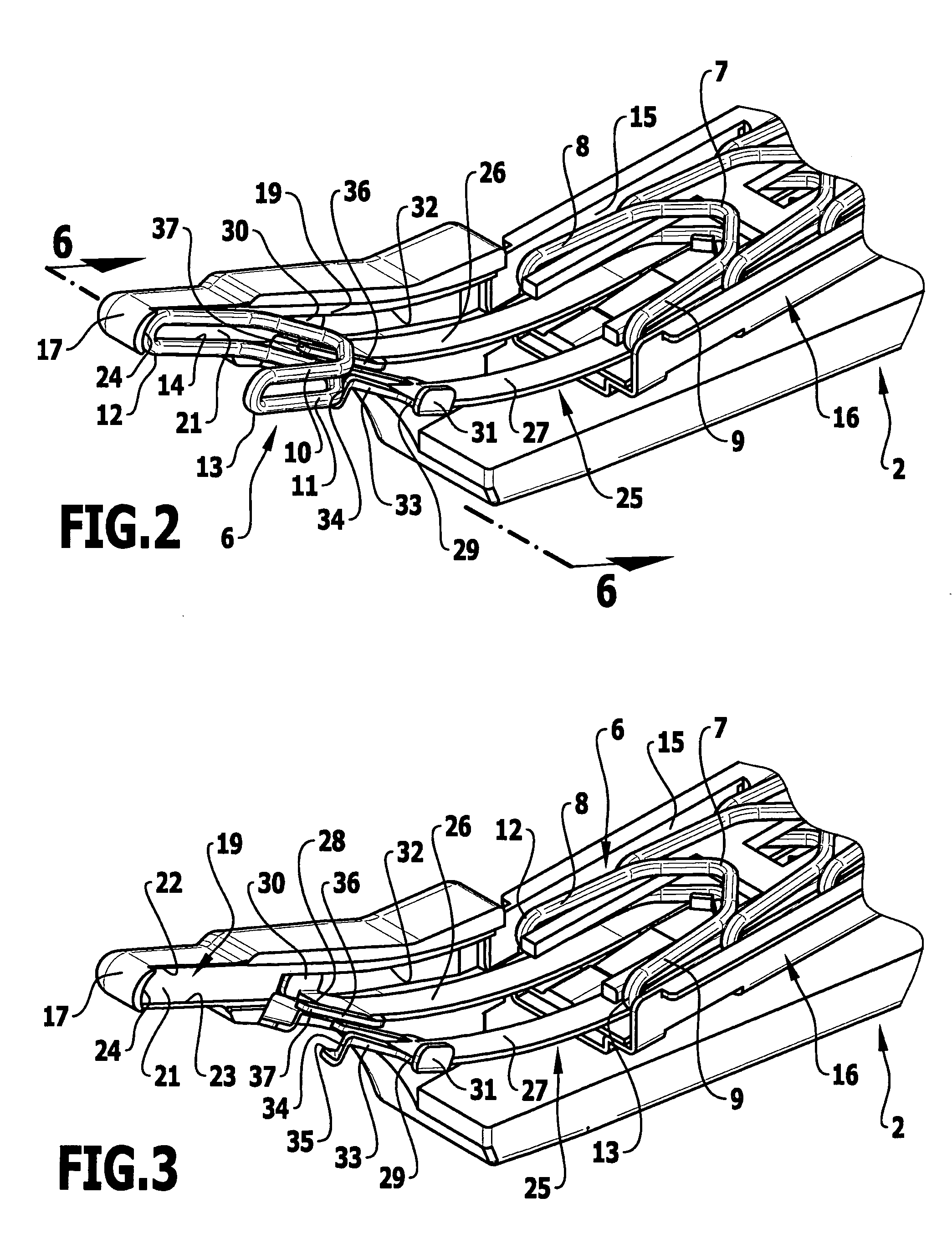
[0015]In such a configuration it is advantageous if the feed element in the form of a strip bears at least one laterally projecting arm, which projects into a longitudinal groove of the instrument and thus guides the feed element in the longitudinal direction.
[0018]The feed element can simply abut against the rear end of the ligature clip to feed the ligature clips, but it is particularly advantageous if the feed element at least partially encompasses the ligature clip in the abutment region on the ligature clip. As a result, the ligature clip is also secured at the rear end embraced by the feed element against pivoting out of the plane of the ligature clip, and therefore is provided with guidance in this region. The feed element thus assumes a double function, namely the function of feeding and the function of guiding the rear end of the ligature clip. This is advantageous in particular when ligature clips are used, the legs of which diverge slightly starting from the bridge section and thus only abut in the region of the free ends of the clamping jaw guide means, while remaining without guidance in the remaining regions of the leg. In this way, a 3-point guidance is obtained for such ligature clips at the two free ends of the legs and at the abutment region of the feed element, so that the ligature clips are securely guided during the entire feeding movement from the. feed guide means into the clamping jaw guide means.
[0019]Ligature clips with diverging legs have the advantage that they provide the surgeon with a larger opening angle for placement on a blood vessel or against any other tissue part. Moreover, in a storage cartridge, in which a number of ligature clips are arranged, these are arranged relatively closely one behind the other and substantially more closely than in the case of ligature clips, in which the legs run parallel to one another and which must therefore adhere to a minimum spacing corresponding to the full structural length of a ligature clip.

Problems solved by technology

However, a disadvantage with these instruments is that the placement region of the ligature clips between the clamping jaws is relatively poorly visible for the surgeon, since it directly adjoins the supply guide means, which is usually located in a cartridge accommodating a number of ligature clips in a shank of the instrument and also projects only slightly laterally beyond this shank because of the very slight inclination.

Method used


Image

  • Surgical instrument for the placement of ligature clips
  • Surgical instrument for the placement of ligature clips
  • Surgical instrument for the placement of ligature clips

Examples


Embodiment Construction

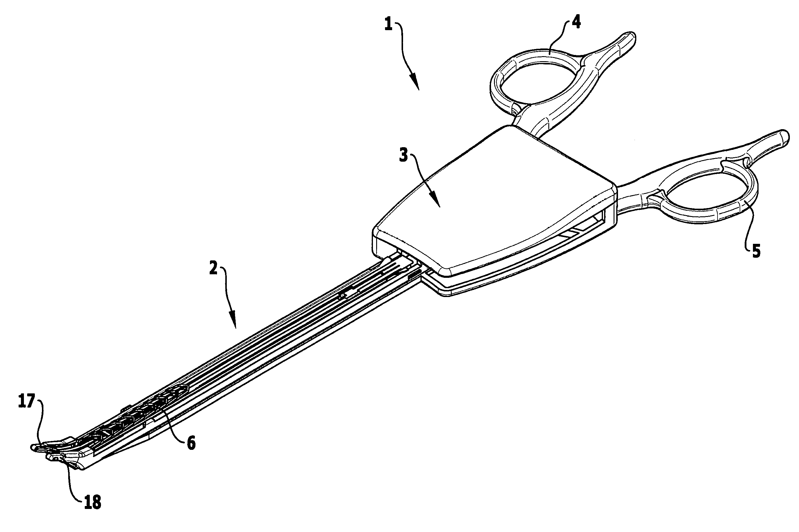
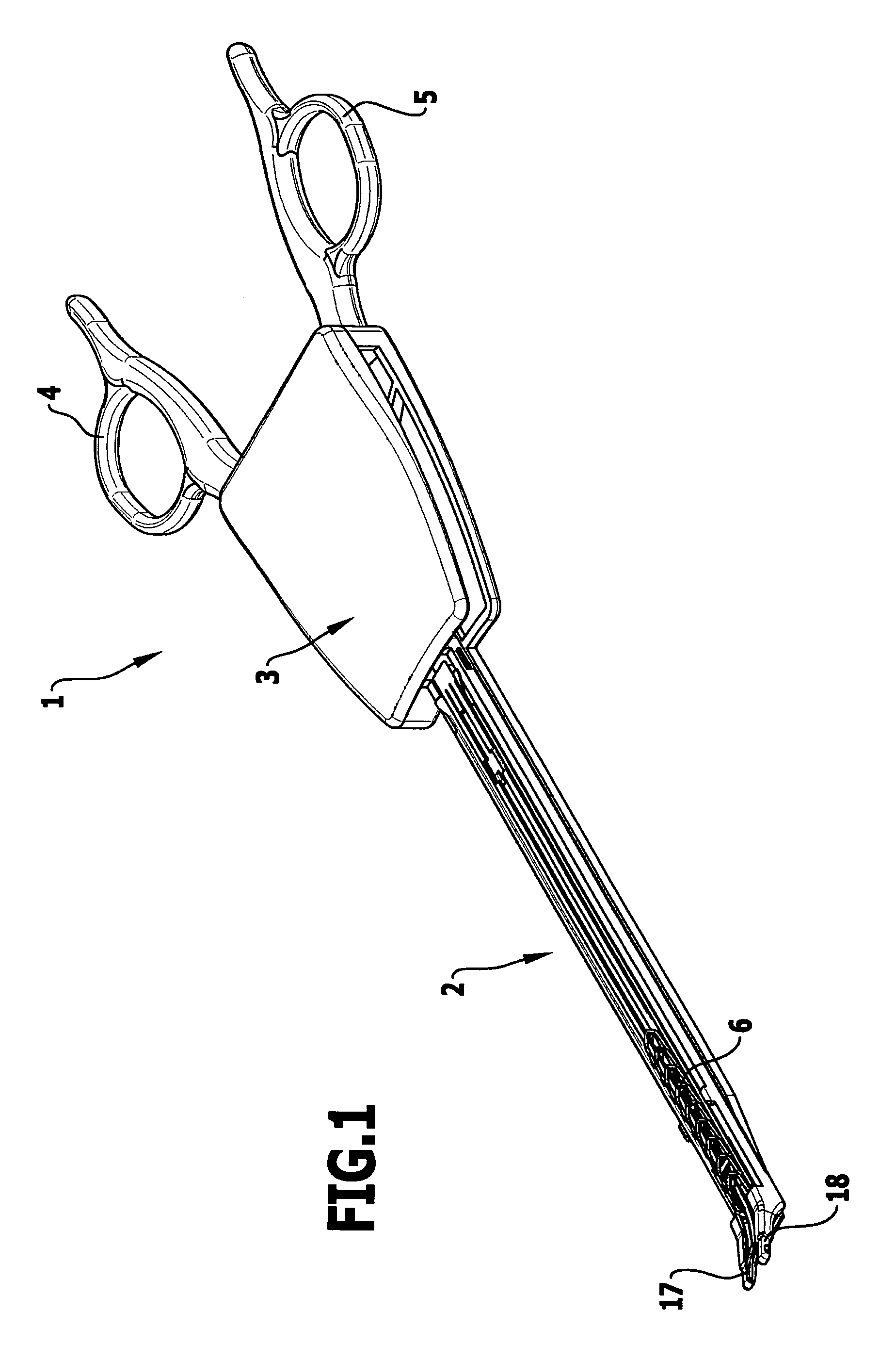
[0029]The instrument 1 shown in FIG. 1 comprises an elongated shank 2 with a handle part 3 at its proximal end. Two handle branches 4, 5, which activate different parts of a feeding means in the interior of the shank 2 by means of a gear mechanism, are pivoted to the handle part 3. A cartridge 16, in which a large number of C-shaped ligature clips 6 are arranged one behind the other, is inserted into the shank 2. The ligature clips 6 used in the present exemplary embodiment are C-shaped in configuration and have two legs 8, 9 arranged next to one another, which are connected to one another by means of a bridge section 7 and diverge slightly from the bridge section 7 to the free ends in such a way that the ligature clips 6 can be arranged one behind the other in the cartridge, so that the free ends of the legs 8, 9 pointing in the distal direction are arranged next to the proximal ends of the legs of the ligature clip 6 located in front of them (FIGS. 2 and 3).

[0030]The ligature clip...


PUM


Abstract

In a surgical instrument for placement of C-shaped ligature clips having two legs running next to one another and connected to one another by means of a bridge-section, with two clamping jaws movable relative to one another, with a supply guide means, along which the ligature clip can be pushed onto the clamping jaws with the free ends of the legs first, with a clamping jaw guide means, which adjoins the supply guide means and in which the ligature clip can be inserted between the clamping jaws, and with a feeding means for advancing a ligature clip out of the supply guide means into the clamping jaw guide means and into an end position between the clamping jaws, in order to improve the guidance of the ligature clips during transfer from the supply guide means into the clamping jaw guide means, it is proposed that the feeding means comprises a feed element, which can be placed against the ligature clip to be fed and is guided in a longitudinal guide means running along its feed path in the transition region from the supply guide means into the clamping jaw guide means.

Description

[0001]This application claims the benefit of German Patent Application No. 10 2009 018 819.3 filed on Apr. 24, 2009.[0002]The present disclosure relates to the subject matter disclosed in German patent application No. 10 2009 018 819.3 of Apr. 24, 2009, which is incorporated herein by reference in its entirety and for all purposes.BACKGROUND OF THE INVENTION[0003]The invention relates to a surgical instrument for the placement of C-shaped ligature clips having two legs running next to one another and connected to one another by means of a bridge section, with two clamping jaws movable relative to one another, with a supply guide means, along which the ligature clip can be pushed onto the clamping jaws with the free ends of the legs first, with a clamping jaw guide means, which adjoins the supply guide means and in which the ligature clip can be inserted between the clamping jaws, and with a feeding means for displacing a ligature clip out of the supply guide means into the clamping ...

Claims


Application Information

Patent Timeline
IPC IPC(8): A61B17/10
CPCA61B2017/2911A61B17/1285
Inventor SCHULZ, PETERMORALES, PEDROWEISSHAUPT, DIETER
Owner AESCULAP AG
Learn More