
Extracorporeal blood circuit

Active Publication Date: 2010-10-28
GAMBRO LUNDIA AB
View PDF23 Cites 34 Cited by
  • Summary
  • Abstract
  • Description
  • Claims
  • Application Information

AI Technical Summary

Benefits of technology

[0010]An advantage of the invention is to provide a blood chamber provided with a filter that is constructionally simple and economical.
[0011]A further advantage is to make available a blood circuit having a filter which can retain solid particles and not retain any air bubbles not dissolved in the liquid flowing in the circuit; any air bubbles can freely rise towards the upper part of the expansion chamber up until reaching a gas-liquid separation zone, e.g. the level of the liquid or a vent provided with a hydrophobic filter.
[0012]A still further advantage is that the invention gives rise to an extracorporeal blood circuit which avoids the risk of introducing solid particles or air bubbles into the patient connected to the circuit.
[0013]In a specific embodiment of the invention, the blood circuit comprises a gas-liquid separation chamber arranged on the venous line returning the blood to the patient, in which a filter configured for retaining the solid particulate contained in the blood flow has a top head which includes a fluid passage conformed asymmetrically with respect to a longitudinal axis of the filter.
[0014]These aims and others besides are all attained by the present invention, as it is characterised in one or more of the appended claims.
[0015]Further characteristics and advantages of the present invention will better emerge from the detailed description that follows, of at least an embodiment of the invention, illustrated by way of non-limiting example in the accompanying figures of the drawings.

Problems solved by technology

One of the drawbacks of the expansion chambers used in the extracorporeal blood circuits of known type is connected with the prevention of air bubbles and / or solid particles present in the blood flow passing through the chamber from being transported towards the patient's vascular circuit.
If during this stage the venous filter retains an air bubble, there is the risk that during treatment, with the patient connected up to the extracorporeal circuit, the air bubble might detach from the venous filter and shift towards the patient.

Method used


Image

  • Extracorporeal blood circuit
  • Extracorporeal blood circuit
  • Extracorporeal blood circuit

Examples


Embodiment Construction

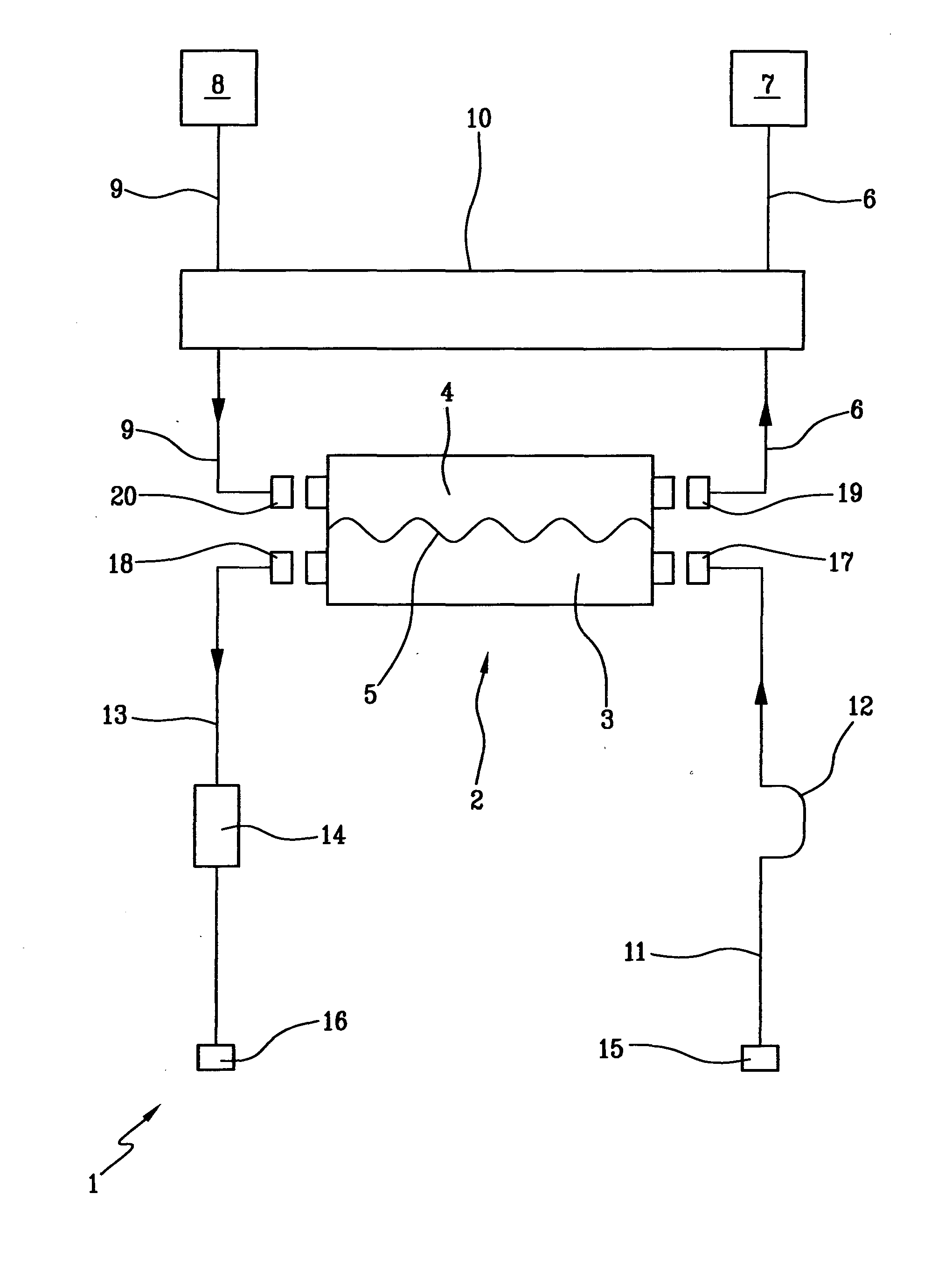
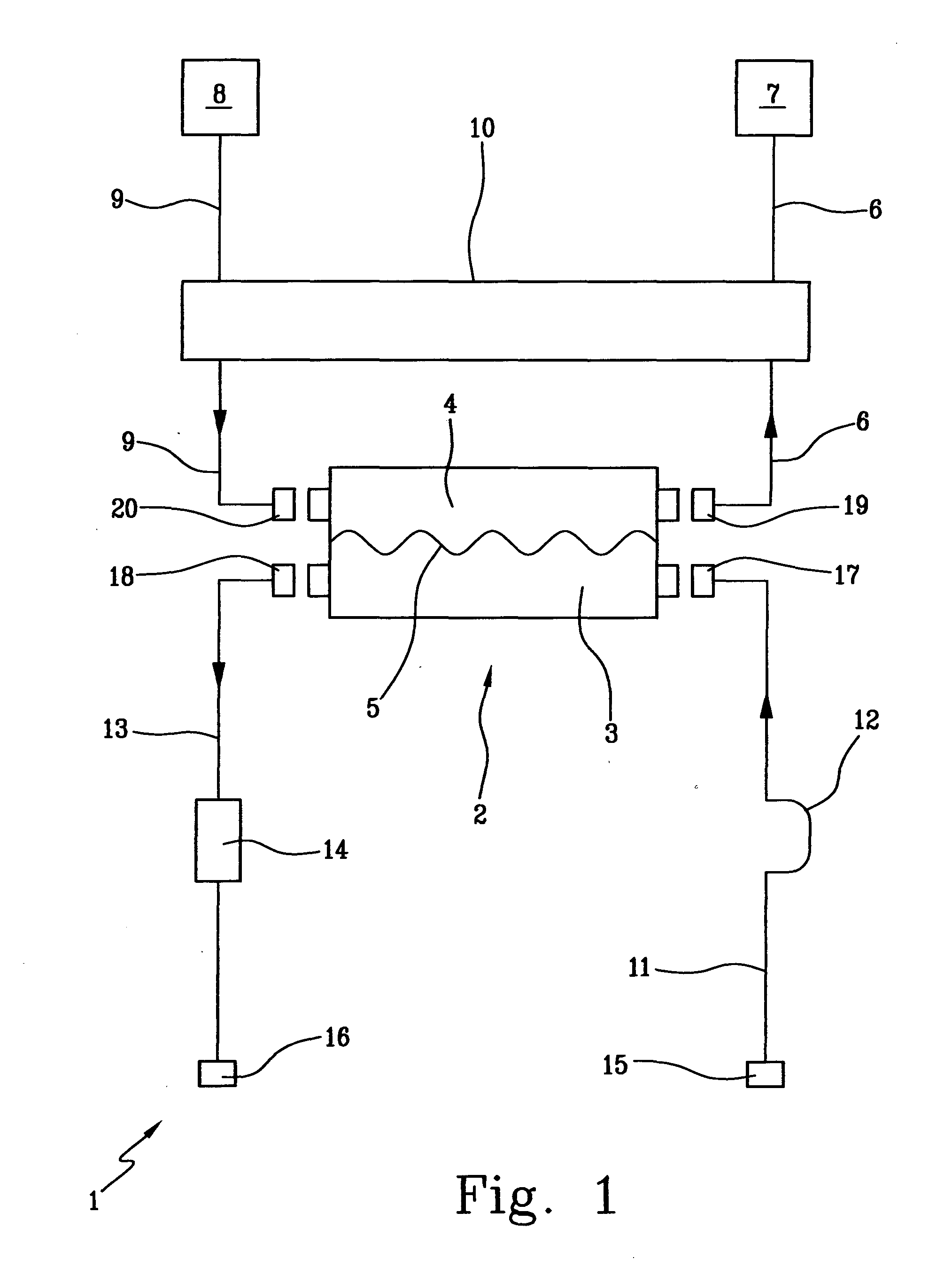
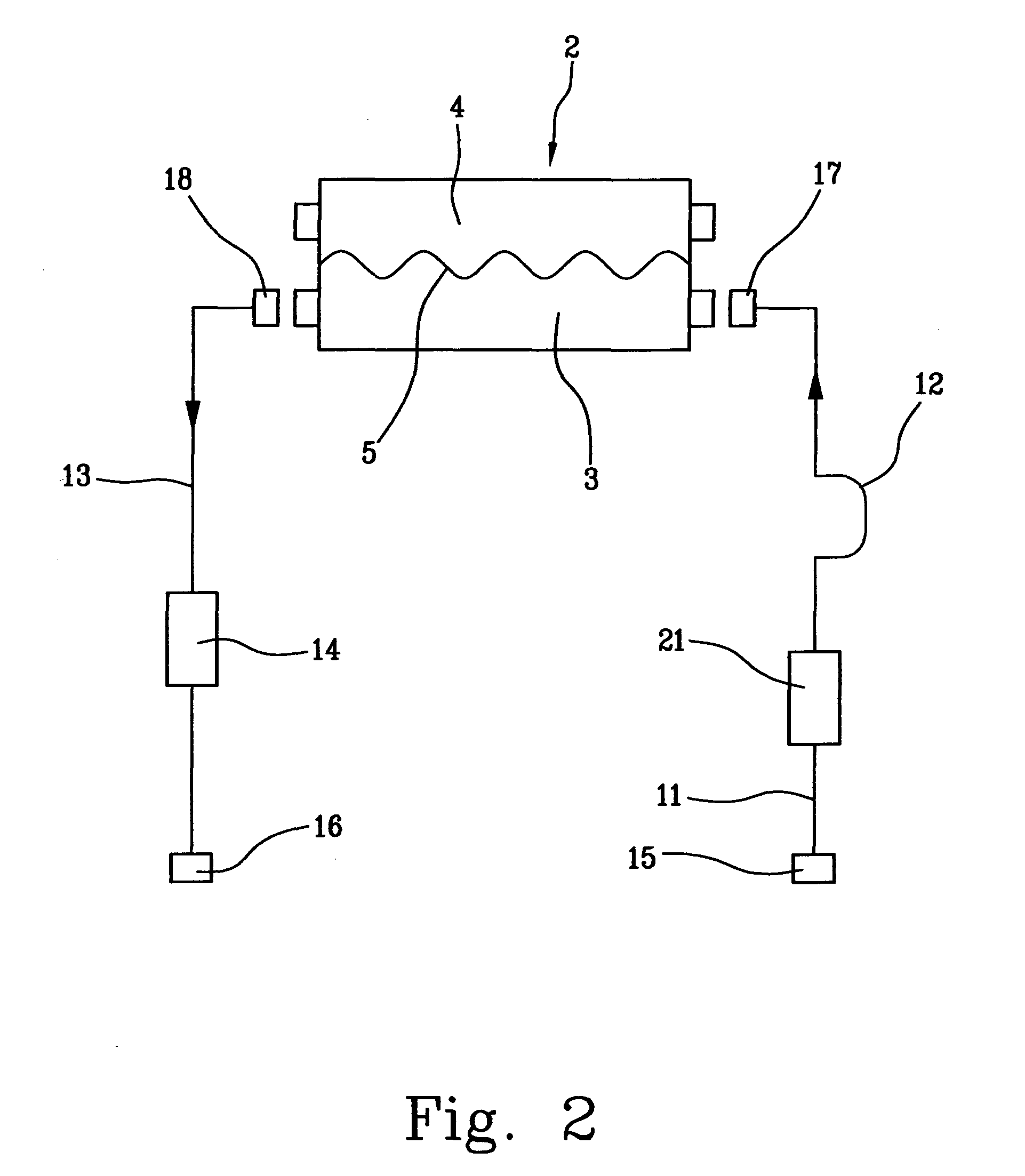
[0028]With reference to FIG. 1, 1 denotes in its entirety an extracorporeal blood treatment apparatus. In the specific case the treatment apparatus 1 comprises a dialysis apparatus. The treatment apparatus 1 comprises a membrane device 2 having a blood chamber 3 and a fluid chamber 4 which are separated from one another by a semipermeable membrane 5. In the specific embodiment the membrane device 2 comprises a dialysis filter. The treatment apparatus 1 comprises a fluid circuit having a used fluid discharge line 6 which connects the fluid chamber 4 to a drainage 7. The used fluid discharge line 6 is provided with sensors and actuators, of known type and not illustrated, which are provided on the used fluid discharge line in any of the dialysis or hemo(dia)filtration apparatus of known type. The treatment apparatus 1 comprises at least a fresh fluid source 8. The source, in the example, comprises a dialysis fluid source. The source 8 can comprise an in-line preparation device of a tr...


PUM

PropertyMeasurementUnit
Diameteraaaaaaaaaa
Flexibilityaaaaaaaaaa
Shapeaaaaaaaaaa

Abstract

An extracorporeal blood circuit, comprising an expansion chamber for air-blood separation, wherein a filter (38) retains the solid particles in the blood. The filter has a trunco-conical filtering wall with a vertical axis surmounted by a top head (43) provided with upper openings (44) conformed and arranged such as to define a fluid passage which is asymmetrical with respect to the vertical axis. The top head does not retain air bubbles internally thereof, thus preventing a situation in which the air bubbles are directed towards an outlet of the expansion chamber and thus towards the patient. The extracorporeal circuit is used in a dialysis apparatus.

Description

BACKGROUND OF THE INVENTION[0001]The invention relates to an extracorporeal blood circuit, in particular an extracorporeal blood circuit provided with an expansion chamber with a blood filter designed for retaining small bodies (for example blood clots) contained in the blood flow.[0002]Specifically, though not exclusively, the invention can be usefully applied in a blood return line (venous line) of the extracorporeal blood circuit used in a dialysis or hemo(dia)filtration treatment, or another extracorporeal blood treatment which might require the use of an extracorporeal blood circuit.[0003]JP 7299136 describes an expansion chamber for a blood circuit having on a bottom thereof a truncoconical filter having a lower opening which communicates with a blood outlet port. The chamber is superiorly closed by a cover which also exhibits a hole for enabling passage of a tube for inlet of the blood into the chamber.[0004]JP 9140788 describes a blood chamber in which a filter has a tubular...

Claims


Application Information

Patent Timeline
IPC IPC(8): A61M1/36B01D35/02B01D61/24
CPCA61M5/165A61M1/3627A61M2205/125A61M2205/123A61M1/362264A61M1/3622A61M1/36224A61M1/362262
Inventor CALEFFI, LUCAFRANZONI, GIUSEPPERIBOLZI, FRANCESCOSAKOTA, RANKOREGA, ANTONIOCALIMERI, ALDOMARCHESI, DAVIDE
Owner GAMBRO LUNDIA AB
Learn More