
Lightning protection system for sectional blades

a protection system and sectional blade technology, applied in wind turbines with parallel air flow, liquid fuel engine components, wind energy generation, etc., can solve the problems of affecting the performance of the blade fiber laminate, the difference in power can give way to skipping the arc, and the blade fiber can be fatally damaged, etc., to achieve easy replacement and inspection.

Active Publication Date: 2010-10-28
GAMESA INNOVATION & TECH SA
View PDF6 Cites 21 Cited by
  • Summary
  • Abstract
  • Description
  • Claims
  • Application Information

AI Technical Summary

Benefits of technology

[0025]Lastly, an added advantage of the proposed design is the easy substitution of the fairings if they are hit by a lightning or the easy inspection of the condition of the intermediate joint through the disassembly of the fairings that are located over the joint.

Problems solved by technology

The problem with leaving conductive materials isolated is the very elevated difference in power that is created between them due to the induction phenomena originated by the lightning bolt while it passes through the lightning arrest system.
This difference in power can give way to skipping the arc, which would be a fatal situation for the fiber laminate of the blade.
These metal elements directly affect the behavior of the blade when faced with lightning strikes, given that they become potential lightning strike attraction points, and therefore must be considered in the design of the lightning strike blade protection system, given that the impact of lightning bolts on the bolted joint could damage it (generate points where cracks could start, damage to threaded joints, damages to possible monitoring systems, jumps of arcs between different metal elements, etc .
A basic protection solution shall consist of connecting the metal elements to the blade's grounding line, but connecting them to the ground makes them more susceptible to a lightning strike.
Not connecting these metal elements to the grounding cable reduces risk, but it must be taken into account that, if a lightning strike were to occur, the current could only be passed on to the grounding cable through an electric arc, with subsequent damage to the joint.
However, these solutions, because they are on the surface of the shell, do not solve the problem of lightning strikes on the connectors of the blade sections, given that the placing of receptors like the one shown on the side of the blade joint would not eliminate the possibility of strikes to the metal elements of the blade joint.

Method used


Image

  • Lightning protection system for sectional blades
  • Lightning protection system for sectional blades
  • Lightning protection system for sectional blades

Examples


Embodiment Construction

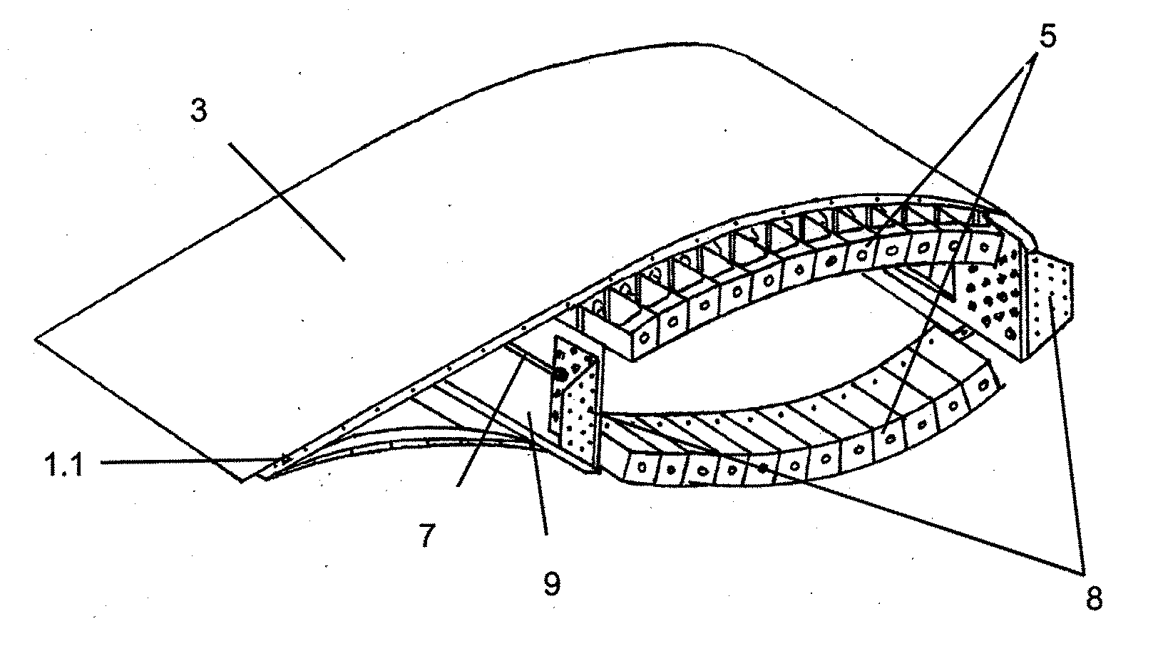
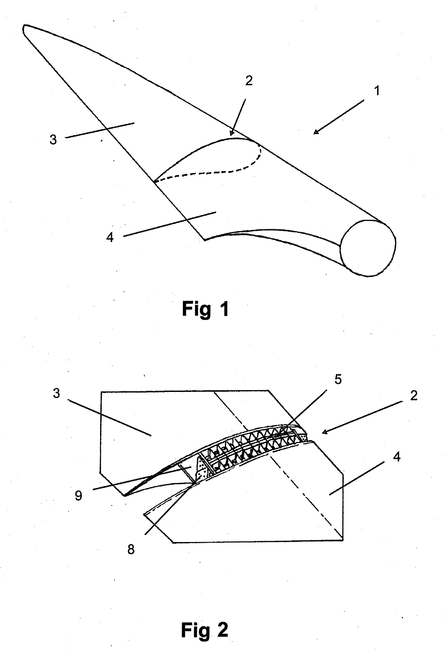
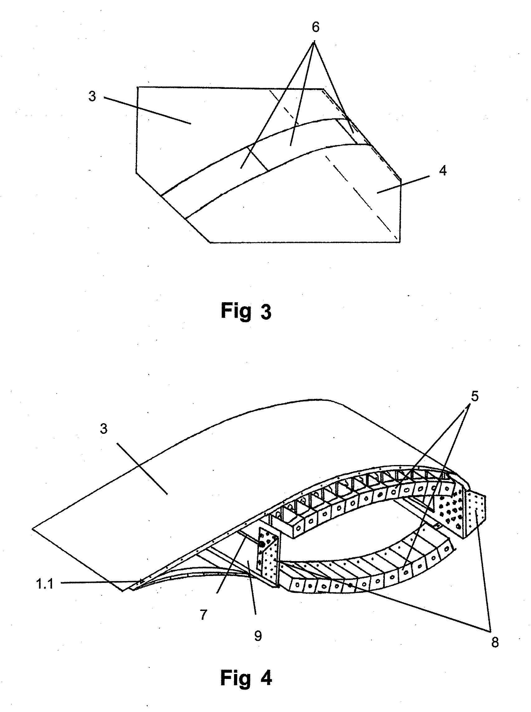
[0015]This invention consists of a lightning protection system for intermediate wind turbine blade joints comprising a metal fairing that covers the blade connector elements, maintaining the aerodynamic geometry of the blade section while protecting the internal connector elements from getting hit by lightning.

[0016]This invention applies to a blade that comprises several modules that are connected with each other through a bolted joint and that has a lightning strike protection system comprised of a receptor on one end of the blade and a grounding cable that extends throughout the length of the structural beam of the blade.

[0017]Once the structural joint between the blade modules is completed, said joint is covered with a series of metal fairings, which achieve a continuity in the surface on the outside of the blade, shielding the volume contained by the fairings where the metal elements of the joint are located, meaning, they create an enclosure where the existing electric field i...


PUM


Abstract

Additional lightning protection system for intermediate wind turbine blade joints comprises a metal fairing that covers the blade connector elements while shielding and protecting the internal connector elements from getting hit by lightning.

Description

OBJECT OF THE INVENTION[0001]This invention is associated with the lightning protection systems implemented in the blades of the wind turbines and, more specifically, with a lightning protection system for sectional blades.BACKGROUND OF THE INVENTION[0002]The blade is the component of a wind turbine that is most vulnerable to being hit by lightning. Numerous factors make the design of an adequate system that prevents damage from getting hit by lightning complex: its great length, the combination of non-conductive materials (such as fiberglass) with other conductive ones (such as carbon fiber), low resistance to the heat of the resins utilized, etc . . .[0003]The need to equipotentialize all of the conductive elements of the blade and connect them to the lightning arrester system for the rest of the wind turbine is covered in the existing bibliography on lightning strikes.[0004]Carbon fiber, as a conductive material, must be equipotentialized with the lightning arrest system. The pro...

Claims


Application Information

Patent Timeline
Patent Type & Authority Applications(United States)
IPC IPC(8): F03D11/00
CPCF03D11/0033Y02E10/721Y02E10/722F03D80/30F05B2240/302Y02E10/72F03D80/00F03D1/065H02G13/00
Inventor AROCENA DE LA RUA, IONCANDELA GAROLERA, ANNASANZ PASCUAL, ENEKO
Owner GAMESA INNOVATION & TECH SA
Learn More