
City Electric Bus Powered by Ultracapacitors

a technology of ultracapacitors and electric buses, which is applied in the direction of electric devices, battery/fuel cell control arrangements, capacitors, etc., can solve the problems of low full charge endurance, so as to improve the control of the entire bus, increase the full charge endurance, and reduce the effect of full charge enduran

Inactive Publication Date: 2010-10-28
SINAUTEC AUTOMOBILE TECH
View PDF8 Cites 33 Cited by
  • Summary
  • Abstract
  • Description
  • Claims
  • Application Information

AI Technical Summary

Benefits of technology

[0004]In currently available technologies, ultracapacitor powered buses are transformed from trolley buses by adding ultracapacitors and AC frequency converter gearing devices. The typical charging voltage range for individual ultracapacitors is 0.9-1.4 Volts. In addition, ultracapacitors can only store a small amount of energy and the full charge endurance is low. Currently available ultracapacitor powered buses do not take full advantage of ultracapacitors storing ability. In some aspects, the invention is directed to curing the deficiency of the currently available ultracapacitor technologies by taking full advantage of ultracapacitor storing ability to increase the full charge endurance and improve the control of the entire bus.

Problems solved by technology

In addition, ultracapacitors can only store a small amount of energy and the full charge endurance is low.
Currently available ultracapacitor powered buses do not take full advantage of ultracapacitors storing ability.

Method used


Image

  • City Electric Bus Powered by Ultracapacitors
  • City Electric Bus Powered by Ultracapacitors
  • City Electric Bus Powered by Ultracapacitors

Examples


Embodiment Construction

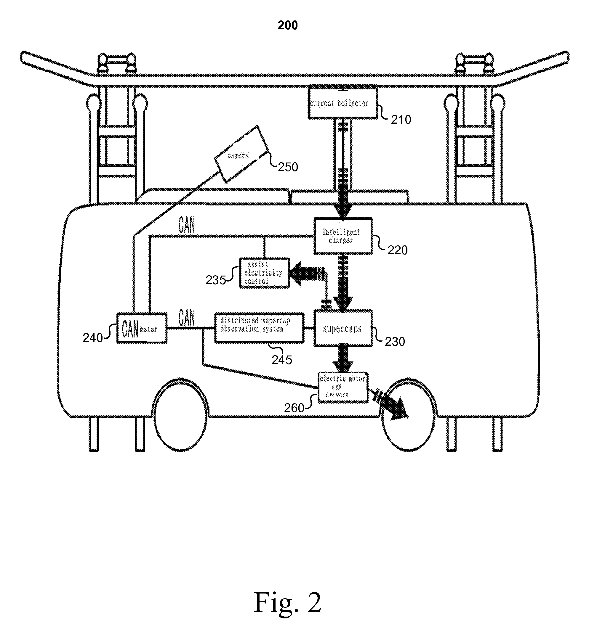
[0014]FIG. 2 illustrates a block diagram of an ultracapacitor powered bus 200, according to an illustrative embodiment of the invention. While FIG. 2 illustrates a bus, other configurations are possible. For example, in some embodiments, ultracapacitors can be used in any vehicle or mobile driven device including, but not limited to, cars, trucks, trains, boats, etc. The bus 200 can include a body structure (not shown), current collector device 210 connected to a pantograph, an intelligent charger module 220, an ultracapacitor module 230, additional electric control units 235, a CAN instrument 240, a distributed ultracapacitor monitoring system 245, a camera 250, and an electric motor and driver module 260. The current collector device 210 can be raised on a pantograph at, for example, bus stops while passengers unload and load. For example, the drive can manually, via a control interface, raise the pantograph or the bus can automatically detect when it is near a charging station (e...


PUM


Abstract

Described are a method and apparatus for charging an electric vehicle powered by ultracapacitors. The vehicle includes a current collector device for collecting power from an external power source, an electric motor module for providing a driving force to the vehicle, an ultracapacitor module, and a charger device. The ultracapacitor module includes one or more ultracapacitors. The ultracapacitor module is coupled to the current collector device for receiving power and is coupled to the electric motor module for providing power. The charger device is connected to the current collector, the ultracapacitor module, and to a temperature signal associated with one or more of the one or more ultracapacitors. The charger device is configured to adjust power supplied to the ultracapacitor module based on the temperature signal.

Description

RELATED APPLICATIONS[0001]This application claims the benefit of and priority to Chinese Patent Application Nos. 200910057119.1 and 200910057120.4, each filed on Apr. 24, 2009, the disclosures of which are incorporated herein by reference in their entirety.FIELD OF THE INVENTION[0002]The present invention relates generally to a method and an apparatus for operating an ultracapacitor powered vehicle.BACKGROUND[0003]Existing ultracapacitor powered buses or automobiles are driven by electric energy stored in ultracapacitors. The ultracapacitor also supplies power to assisting operating devices. The fundamental principles are similar to those of the trolleybus, as is shown in FIG. 1. Vehicles powered by ultracapacitors can charge when they are stopped at stations (e.g., bus stations) in a traffic system. When the ultracapacitor needs to charge, it can utilize the existing rectified DC network for trolleybuses as the power source or, after reducing (or lifting) voltage and rectifying, ca...

Claims


Application Information

Patent Timeline
IPC IPC(8): H02J7/00B60L5/04
CPCB60L3/0046B60L11/005Y02T90/16Y02T10/7022B60L2260/56B60L50/40B60L58/24Y02T10/70
Inventor GONG, ZHENGDALIANG, QUANSHUNHUA, LIMIAO, XIAO LIHENG, JIANPO
Owner SINAUTEC AUTOMOBILE TECH
Learn More