
Method and Apparatus Using Distributed Raman Amplification and Remote Pumping In Bidirectional Optical Communication Networks

a technology of optical communication network and distributed raman, which is applied in the field of optical fiber communication network, can solve the problems of limiting the maximum transmission distance (or reach) between the olt and the farthest onu/ont, limiting the typical gpon deployment to a 1:32 split ratio and km reach, negating some of the advantages of pon systems, etc., to achieve the effect of improving the loss budget, extending the reach, and increasing the split ratio

Active Publication Date: 2010-10-21
OFS FITEL LLC
View PDF14 Cites 10 Cited by
  • Summary
  • Abstract
  • Description
  • Claims
  • Application Information

AI Technical Summary

Benefits of technology

[0015]In accordance with a first aspect of my invention, I propose to use remote pumping and distributed Raman amplification at the upstream optical signal wavelength and / or at the downstream optical signal wavelength of a PON to improve its loss budget, thereby extending its reach and / or increasing its split ratio.
[0019]In still another embodiment of the first aspect of my invention, the passive optical node includes a wavelength-sensitive device that prevents any significant amount of the pump light from entering the receivers of the second terminals. In one configuration of this embodiment, the wavelength sensitive device comprises a bandpass filter; in another configuration, it comprises a reflector, which reflects pump light back into the fiber (after it has propagated through the fiber), thereby also providing additional Raman amplification of the signals.
[0022]In one embodiment of the third aspect of my invention, the node includes a wavelength-sensitive device that prevents any significant amount of the pump light from entering the receivers of the second terminals. In one configuration of this embodiment, the wavelength sensitive device comprises a bandpass filter; in another configuration, it comprises a reflector configured to reflect pump light back into the fiber (after it has propagated through the fiber), thereby to also provide additional Raman amplification of the first and second signals.

Problems solved by technology

However, the maximum transmission distance (or reach) between the OLT and the farthest ONU / ONT, as well as the split ratio, are currently limited by various physical layer limitations and the PON protocol.
For example, although the GPON standard (ITU-T G.984) allows for a logical reach of 60 km and maximum split ratio of 1:128, a 28 dB loss budget currently limits typical GPON deployments to a 1:32 split ratio and km reach.
The reach extension approaches considered in G.984.6 require the use of electrically powered units in the outside plant containing well-known optical amplifiers or optical-to-electrical-to-optical (OEO) repeaters, but this design requirement negates some of the advantages of PON systems and may not always be practical or cost effective for network service providers / operators, particularly in certain environments where no electrical powering is available.

Method used


Image

  • Method and Apparatus Using Distributed Raman Amplification and Remote Pumping In Bidirectional Optical Communication Networks
  • Method and Apparatus Using Distributed Raman Amplification and Remote Pumping In Bidirectional Optical Communication Networks
  • Method and Apparatus Using Distributed Raman Amplification and Remote Pumping In Bidirectional Optical Communication Networks

Examples


example

[0076]This example demonstrates a reach-extended, remotely-pumped, distributed Raman gain GPON, which provided symmetric 2.488 Gb / s transmission over 60 km of fiber. The network was compatible with ITU G.984. Various materials, dimensions and operating conditions are described by way of illustration only and, unless otherwise expressly stated, are not intended to limit the scope of the invention.

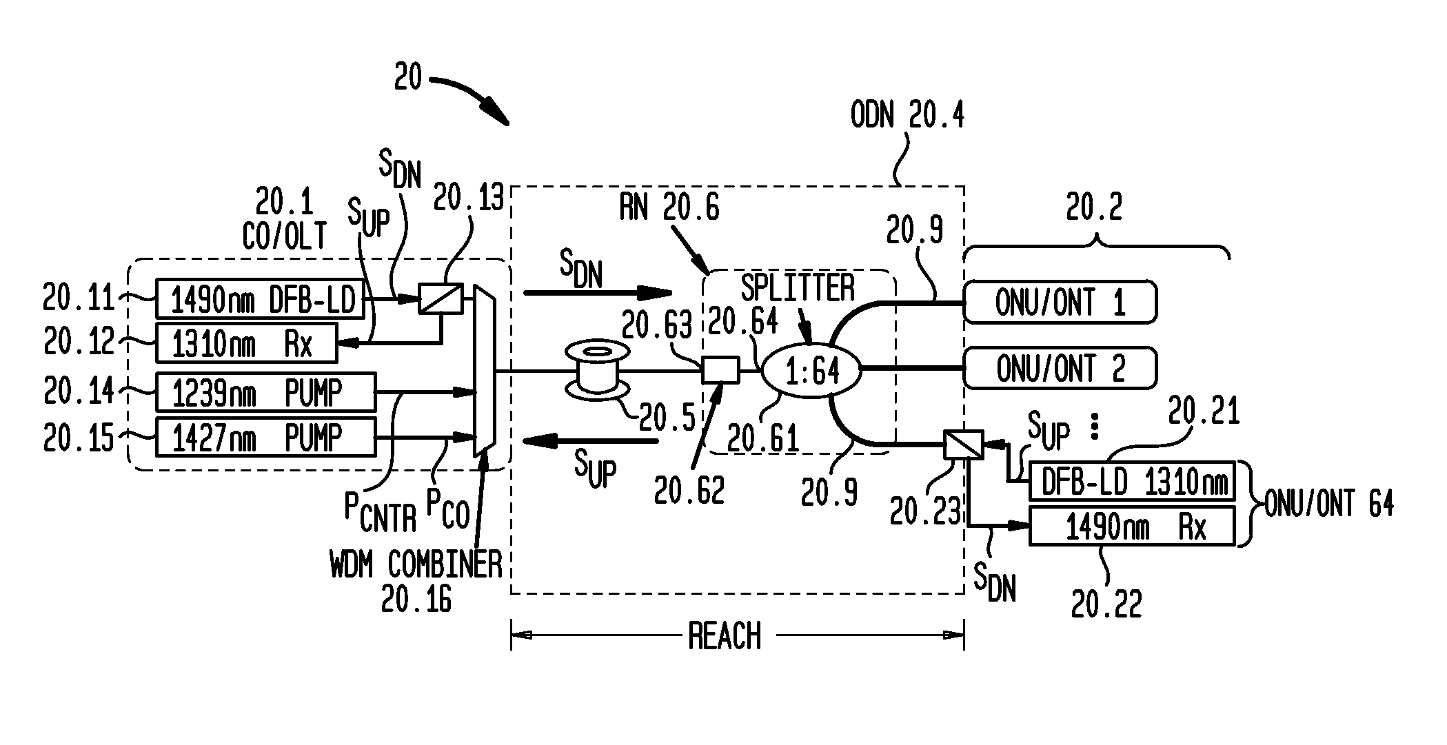
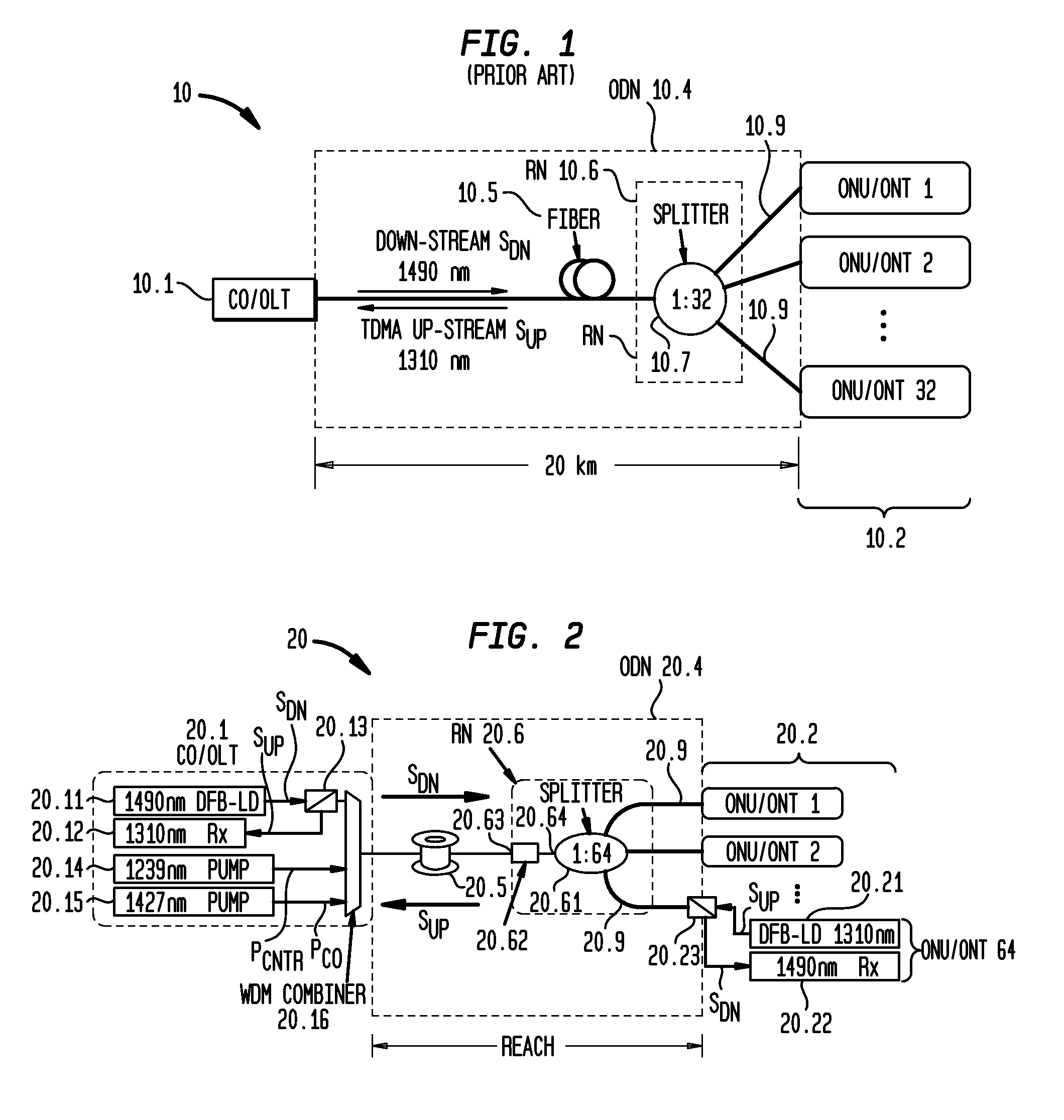
[0077]FIG. 2 is a schematic diagram of the experimental apparatus, showing a CO / OLT 20.1 optically coupled to a RN 20.6 by means of 60 km of Zero Water Peak AllWave® single-mode optical fiber 20.5 and a multiplicity of ONU / ONTs 20.2. The OLT comprised (i) a transmitter 20.11 including a DFB LD for generating a downstream optical signal at 1490 nm, (ii) a receiver 20.12 including an APD for detecting upstream optical signals at 1310 nm, (iii) a WDM combiner 20.16, and (iv) Raman pump sources 20.14 and 20.15 that provided remote pumping of distributed Raman gain in fiber 20.5. In particular, p...


PUM


Abstract

A bidirectional optical communications network comprises an optical transmission fiber for carrying a downstream signal at a first wavelength and a multiplicity of upstream signals at a second, different wavelength. The fiber is characterized by distributed Raman gain over at least an extended portion of its length. A first terminal, optically coupled to one end of the fiber, includes a first transmitter for generating the downstream signal, a first receiver for detecting the upstream signals, and at least one pump source for generating pump light that provides Raman amplification to either the downstream signal or the upstream signal or both. A multiplicity of second terminals, optically coupled to another end of the fiber, each includes a second transmitter for generating one of the upstream signals, and a second receiver for detecting a downstream sub-signal. A passive optical node is configured to (i) split the downstream signal into a multiplicity of downstream sub-signals each propagating at the first wavelength to a separate one of the second terminals and (ii) to combine each of the upstream signals from each of the second terminals onto the fiber for transmission to the first terminal. In another embodiment, the network is a GPON compatible with current ITU standards.

Description

CROSS-REFERENCE TO RELATED APPLICATIONS[0001]This application claims priority from Provisional Application Ser. No. 61 / 169,510 filed on Apr. 15, 2009 and entitled “Method and Apparatus for Remotely-Pumped Passive Optical Network System for Extending Reach.”BACKGROUND OF THE INVENTION[0002]1. Field of The Invention[0003]This invention relates to optical fiber communication networks, and, more particularly, to method and apparatus using distributed Raman amplification and remote pumping for extending the reach and / or increasing the split ratio of passive optical networks.[0004]2. Discussion of The Related Art[0005]A passive optical network (PON) is a point-to-multipoint, fiber-to-the-premises, broadband network architecture in which unpowered optical splitters arc used to enable a single optical fiber to serve multiple customer premises. As shown in FIG. 1, a typical PON 10 includes an optical line terminal (OLT) 10.1 at the service provider's central office (CO) and a multiplicity of...

Claims


Application Information

Patent Timeline
Patent Type & Authority Applications(United States)
IPC IPC(8): H04J14/02H04B10/00H04B10/27H04B10/272H04B10/29H04B10/297H04B10/85
CPCH04B10/2503H04J14/0282H04J14/0221H04B10/2916H04B10/2589
Inventor ZHU, BENYUAN
Owner OFS FITEL LLC
Learn More