
Internal combustion engine

Inactive Publication Date: 2010-10-21
MITSUBISHI ELECTRIC CORP
View PDF20 Cites 9 Cited by
  • Summary
  • Abstract
  • Description
  • Claims
  • Application Information

AI Technical Summary

Benefits of technology

[0008]The present invention is devised to solve the problem described above, and has an object of providing an internal combustion engine for improving fuel-economy performance in any of the case where supercharging performed by an electric supercharger is required and the case where the supercharging is not required.
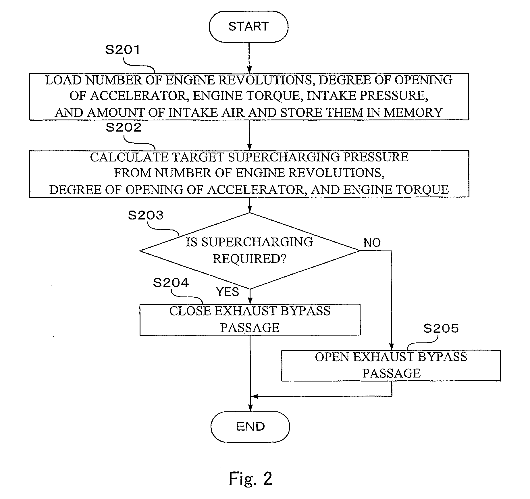
[0010]The internal combustion engine according to the present invention provides the following effects. When the supercharging performed by the electric supercharger is not required, the exhaust flow is caused to bypass the exhaust turbine to lower an exhaust resistance, thereby improving fuel-economy performance. On the other hand, when the supercharging performed by the electric supercharger is required, the exhaust bypass passage is quickly closed to allow the exhaust turbine to be rotated by the exhaust gas. Then, the supercharger is rotated with a combination of an exhaust gas energy and an energy of the electric motor to control a supercharging pressure to a target supercharging pressure, thereby improving the fuel-economy performance.

Problems solved by technology

The electric motor rotates in the case where a desired supercharging pressure is not obtained because of the shortage of an exhaust gas when supercharging is required or in the case where the supercharger rotates at a low speed.
As a result, fuel-economy performance is degraded.
However, it is necessary to increase the supercharging pressure by the rotation of the electric motor in the meantime, resulting in consumption of a significant amount of power.
Therefore, there is a problem that the fuel-economy performance is likely to be consequently degraded.

Method used


Image

  • Internal combustion engine
  • Internal combustion engine
  • Internal combustion engine

Examples


first embodiment

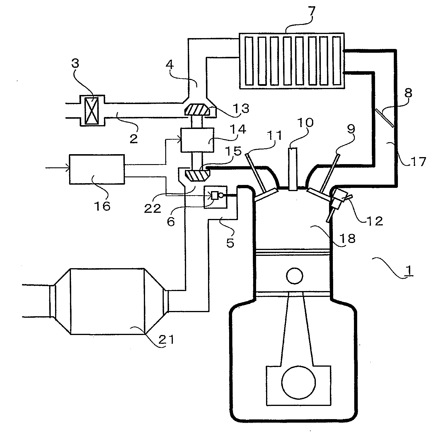
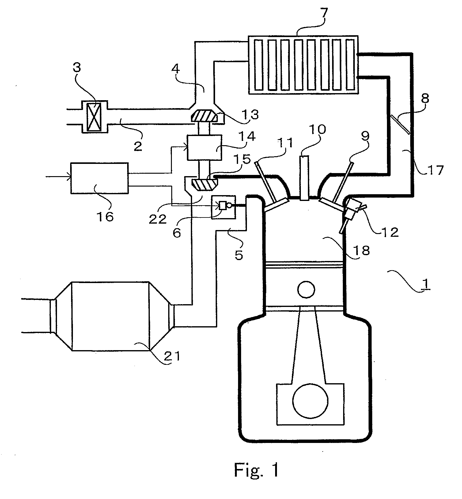
[0017]FIG. 1 is a schematic configuration diagram of an internal combustion engine including an electric supercharger according to a first embodiment of the present invention.

[0018]The internal combustion engine, that is, an engine 1 of the present invention is a multi-cylinder engine. However, FIG. 1 illustrates a cross section of only one of the multiple cylinders.

[0019]The engine 1 is of a type that injects a fuel into a cylinder 18 by an injector 12. A larger amount of intake air is supercharged by a supercharger (compressor impeller) 13 with electric-motor assistance of an electric motor 14 described below. In this manner, not only an increase in output but also an increase in fuel economy can be realized.

[0020]The engine 1, to which the present invention is applied, is not only a direct injection engine for injecting the fuel into the cylinder 18. The present invention is also applicable to a port injection engine for injecting the fuel into an intake passage 17 at downstream ...


PUM


Abstract

Provided is an internal combustion engine for improving fuel-economy performance in any of the case where supercharging performed by an electric supercharger is required and the case where the supercharging is not required. The internal combustion engine includes: an electric supercharger; a supercharger; an electric motor; and a controller, the electric supercharger being for compressing an intake air by rotation of the supercharger caused with rotation of the exhaust turbine by an exhaust gas energy to perform supercharging and for rotationally driving the supercharger with electric-motor assistance by the electric motor; an exhaust bypass passage provided to bypass the exhaust turbine; and an opening and closing the exhaust bypass passage unit. In the internal combustion engine, the opening and closing the exhaust bypass passage unit opens the exhaust bypass passage until the supercharging is started by the electric supercharger.

Description

BACKGROUND OF THE INVENTION[0001]1. Field of the Invention[0002]The present invention relates to an internal combustion engine including a supercharger provided on an intake passage, which is electric-motor-assisted by an electric motor.[0003]2. Description of the Related Art[0004]For improving fuel economy of automobiles, a technology of providing a supercharger, which is driven by an electric motor, on an intake passage to increase an output of an engine (internal combustion engine) is known. The electric motor is provided on a shaft of a turbine and a compressor and has the following characteristics. The electric motor rotates in the case where a desired supercharging pressure is not obtained because of the shortage of an exhaust gas when supercharging is required or in the case where the supercharger rotates at a low speed. In the case where the turbine is rotated by the exhaust gas to successfully obtain the desired supercharging pressure, the electric motor is rotated by the e...

Claims


Application Information

Patent Timeline
IPC IPC(8): F02C6/12F02C7/32
CPCF02B37/14Y02T10/144F02B39/10F02B37/18Y02T10/12
Inventor TANAKA, HIDEYUKIINOUE, NORIYUKIAKASHI, YOHEI
Owner MITSUBISHI ELECTRIC CORP
Learn More