[0015]According to claim 1 of the invention, the electrical component accommodated in the accommodating portion to be press-retained can be urged by the predetermined urging force according to the thickness of the electrical component or the number of terminals thereof, by the socket cover which is disposed movably to be close to the socket body and apart from the socket body when the socket cover is closed. Consequently, even in the case of different thickness of the electrical component or different number of terminals thereof, the electrical component can be pressed to be fixed by the appropriate urging force while avoiding deficient pressing or excessive pressing, thereby achieving stable
electrical connection.
[0016]Furthermore, according to claim 2 of the invention, in the state of including the socket body which includes the first shaft holes formed on the side of the one side end portion thereof, and the socket cover which is rotatably attached to the socket body, by aligning the center axis of each of the second shaft holes formed on the side of the one side end portion of the socket cover with the center axis of each of the first shaft holes of the socket body, to insert the shaft through the second shaft holes and the first shaft holes, the cross-sectional shape of each of the first shaft holes of the socket body is formed in the long hole shape, to enable the shaft to be moved, in the shaft holes of the socket body, to be close to the socket body and apart from the socket body, and furthermore, the shaft is urged to be close to the socket body by the urging device when the socket cover is closed. Consequently, the shaft is permitted to move in the shaft holes until the urging force by the urging device on the shaft to be close to the socket body is balanced with the
counterforce from the electrical component to be spaced from the socket body. Thus, in the case in which the socket cover is closed so that the electrical component accommodated in the accommodating portion of the socket body is pressed to be fixed, the height of the accommodating portion, which is formed depending on a distance from an upper surface of the accommodating portion to a bottom surface of the socket cover, is set in advance to be equal to or lower than a
lower limit value of a height dimension of the electrical component, so that even in the case in which the height dimension of the electrical component is a minimum value within tolerance, the electrical component can be pressed to be fixed by the appropriate urging force while avoiding deficient pressing. Furthermore, in the case in which the height dimension of the electrical component is larger than the minimum value within the tolerance, the electrical component can be pressed to be fixed by the appropriate urging force while avoiding excessive pressing, thereby achieving the stable
electrical connection.
[0017]Furthermore, according to claim 3 of the invention, the movable portion at the tip end of each
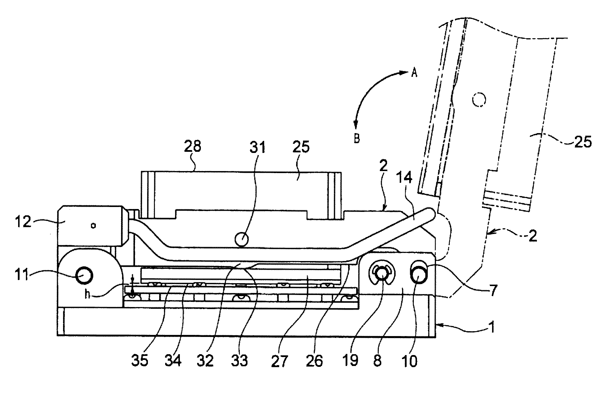
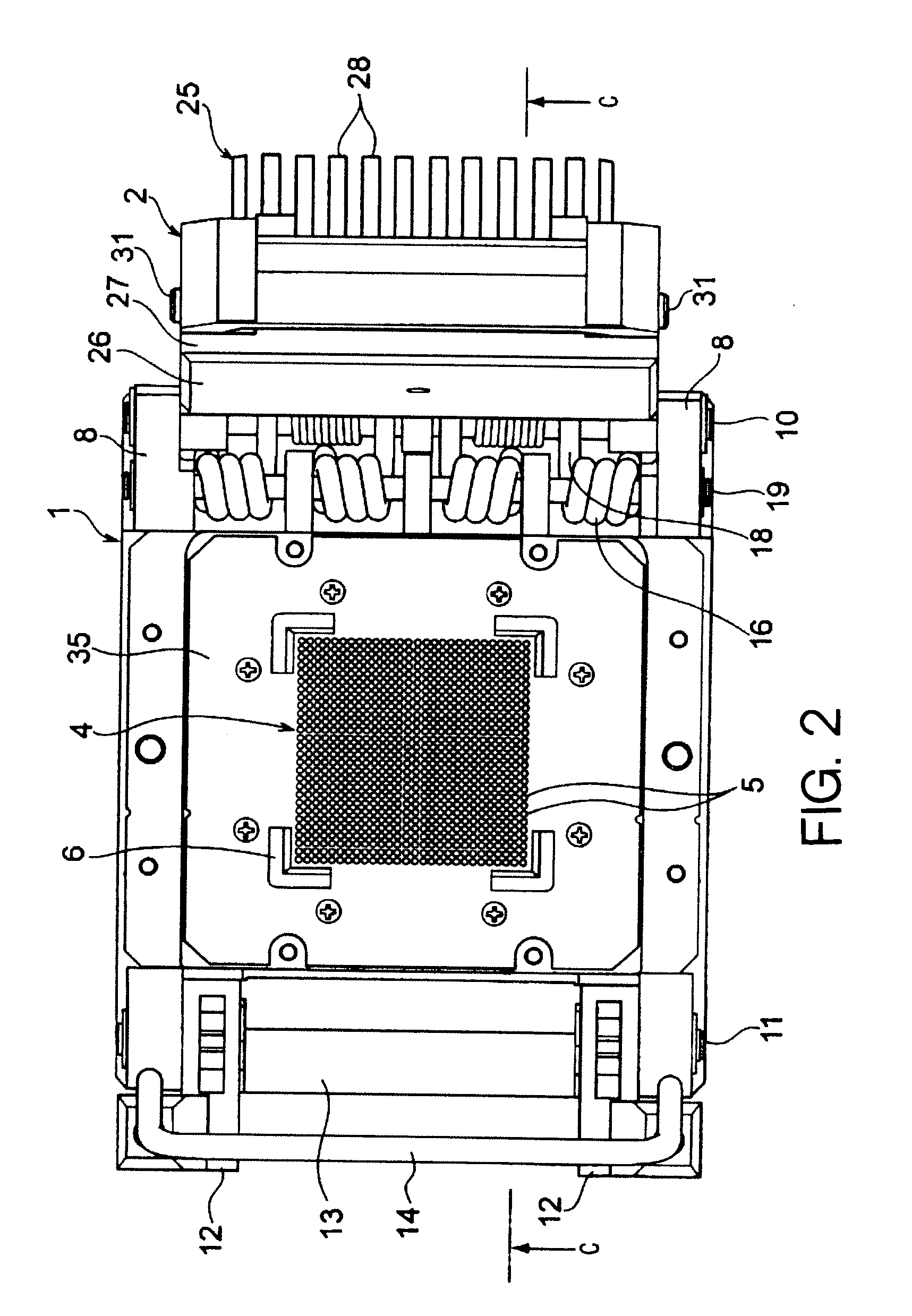
torsion spring can urge the socket cover to be close to the socket body, by the urging device including the torsion springs axially supported by the fixed axis disposed on the one side end portion of the socket body, in which the fixed portion at the base end thereof is fixed to the socket body. Consequently, the urging device can be formed in a simple structure. Moreover, the pressing of the electrical component by the socket cover is performed by retaining the other side end portion of the socket cover while urging the one side end portion thereof by the torsion springs. Therefore, by utilizing a lever principle with the other side end portion as a support, the electrical component can be pressed by a predetermined force even if an elastic force of the torsion springs is small.
[0018]Still further, according to claim 4 or claim 5 of the invention, the urging force by the urging device can be adjusted by the urging force adjusting device additionally disposed to the socket body. Consequently, plural types of electrical components of different thickness or different number of pins can be urged by the appropriate urging forces according to the different thickness thereof or the different number of pins thereof.
[0019]Even still further, according to claim 6 of the invention, the fixed portion on the base end can be pressed or press-released, to be displaced in the direction of changing the urging force by the torsion springs, by the urging force adjusting device provided in the socket body, to thereby change the initial deflection amount of the torsion springs. Consequently, it is possible to change freely a deflection amount of the fixed portion on the base end to thereby variably adjust the urging force of the torsion springs.
[0020]Moreover, according to claim 7 of the invention, the electrical component accommodated in the accommodating portion can be pressed by the lower surface of the
heat sink which is swingably mounted into the open portion disposed to pass from the lower surface of the socket cover to the upper surface thereof. Consequently, even in the case in which the socket cover becomes oblique to the electrical component as a result that the one side end portion of the socket cover is vertically moved, the
heat sink mounted on the socket cover is swung, so that the socket cover can always be held to be parallel with the electrical component and the electrical component can be evenly pressed over the whole thereof. Therefore, any urging device for the heat sink is not necessary to be disposed separately, and accordingly, the heat sink can be enlarged for that space, thereby improving the dissipation performance of the heat sink. Furthermore, the structure can be simplified and the number of parts can be decreased.

