
Method and device for locating function-supporting tissue areas in a tissue region

Active Publication Date: 2010-10-07
CARL ZEISS MEDITEC AG
View PDF4 Cites 10 Cited by
  • Summary
  • Abstract
  • Description
  • Claims
  • Application Information

AI Technical Summary

Benefits of technology

[0015]As a result of the inventive recording of at least one image with measurement illumination and at least one image without measurement illumination during the stimulation (or without stimulation), information is also obtained relating to what influence the other illumination has on the image recorded with the measurement illumination, in addition to the information relating to the functional tissue areas. Thus, there generally also is background illumination while the image is recorded with the measurement light, with the background illumination allowing the medical practitioner to observe the tissue region. Moreover, scattered light from light sources not provided directly for illuminating the tissue region is also incident on the tissue region and is reflected by the latter. Forming the difference of an image recorded with measurement light during the stimulation and an image recorded without measurement light during the stimulation can eliminate or at least reduce these influences of the surroundings from the image recorded with measurement light, and this increases the contrast in the stimulation image used to locate the functional tissue areas. The elimination or reduction of the influences of the surroundings is improved as the difference between the spectral distribution of the measurement light and the surrounding light increases. Monochrome illumination or illumination with only few wavelength components is particularly suitable.
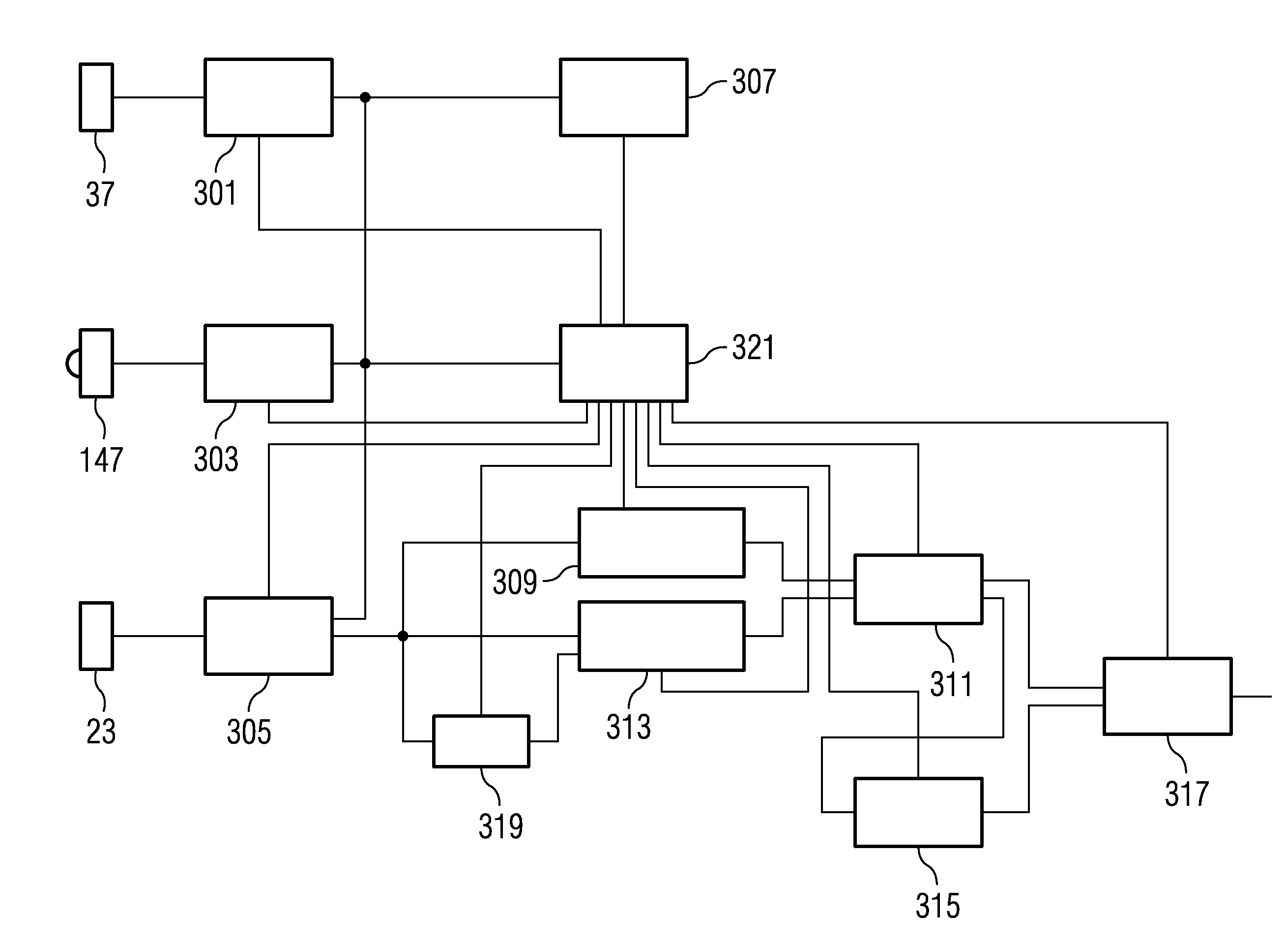
[0039]As per the second aspect of the invention, the device according to the invention comprises a topography acquisition unit, which determines topography data of the tissue region. It furthermore comprises a correction unit, which is connected to the electronic image sensor for receiving the images and to the topography acquisition unit for receiving the topography data. The correction unit is designed to determine, from an image recorded during the stimulation, an image corrected on the basis of the determined topography data. The correction unit is connected to the evaluation unit for outputting the corrected image from the stimulation image obtained during the stimulation. The device according to the invention as per the second aspect of the invention can be used independently of the first aspect of the invention or can be combined with a device designed as per the first aspect of the invention. The combination of devices as per the first aspect of the invention and as per the second aspect of the invention in particular allows the generation of particularly contrast-rich stimulation images. In the process, the correction can already be undertaken on the images recorded with the measurement light. Alternatively, it is also possible for the correction to be undertaken only on a difference image that was obtained from an image recorded with measurement light and an image recorded without measurement light.

Problems solved by technology

However, such methods involving contact have limitations that limit the options for application.
This cannot achieve a high-resolution display of functional tissue areas.
Furthermore, a method involving contact is inevitably associated with risks resulting from contacting the tissue with an object made of tissue-extraneous material.
However, it is extremely difficult to carry out the optical imaging methods described in the aforementioned documents because the changes in the reflected light connected to the functional stimulation are of low intensity.
Moreover, use is generally made of expensive monochromes (CCD cameras) with a high grayscale resolution (24 bit) and relatively long integration times. Locating functional tissue areas using this takes up relatively large amounts of time, which is particularly disadvantageous if this increases the duration of the operation.
Therefore, overall, it is very difficult to generate contrast-rich images of functional regions in a short time using the described optical imaging methods.

Method used


Image

  • Method and device for locating function-supporting tissue areas in a tissue region
  • Method and device for locating function-supporting tissue areas in a tissue region
  • Method and device for locating function-supporting tissue areas in a tissue region

Examples


Embodiment Construction

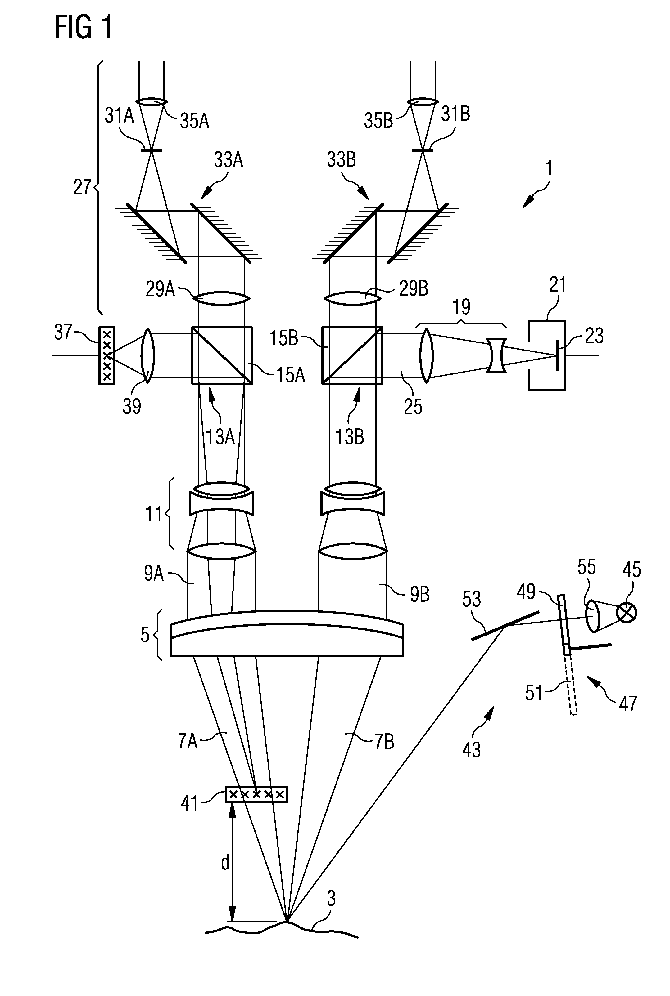
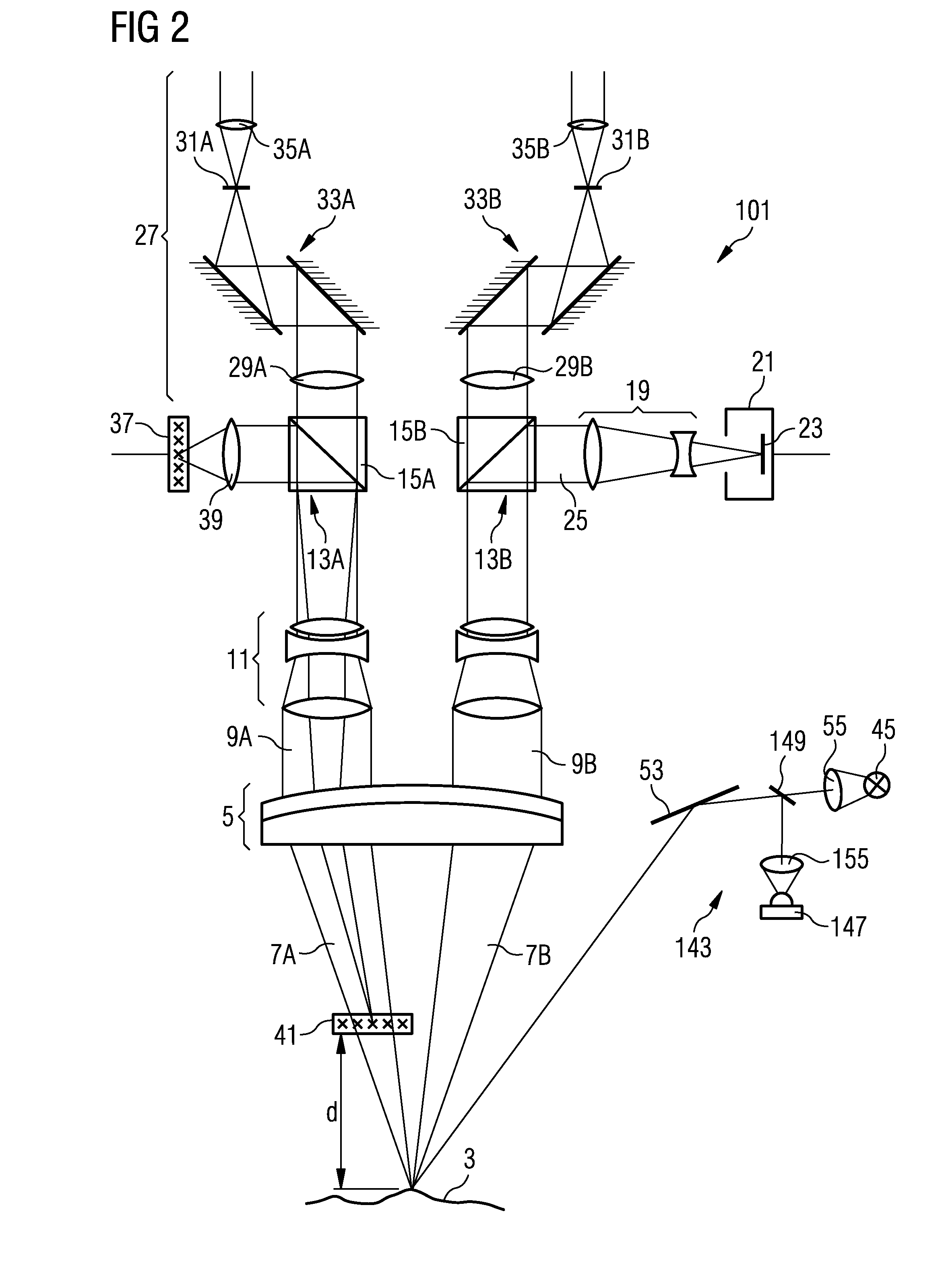
[0053]In the following text, the basic design of a device according to the invention for locating functional tissue areas in a tissue region will be explained with reference to FIGS. 1 to 4 using the example of an operation microscope into which the device according to the invention is integrated.

[0054]The operation microscope 1 shown in FIG. 1 comprises as essential components an objective 5, which should be made to face an observation object 3 and, in the present exemplary embodiment, is illustrated as an achromatic lens designed from two mutually cemented partial lenses. The observation object 3, namely the tissue region whose functional tissue areas are intended to be located, is arranged in the focal plane of the objective 5 such that the tissue region 3 is focused at infinity, that is to say a divergent bundle of rays 7 emanating from the tissue region 3 is converted into a parallel bundle of rays 9 when passing through the objective 5.

[0055]Instead of using only one achromati...


PUM


Abstract

Functional tissue areas in a tissue region are located by illuminating the tissue by measurement illumination. Stimulation in the functional tissue areas leads to a change in at least one optical property of the reflected measurement illumination compared to the original measurement illumination. The functional tissue areas are located based on the change in the at least one optical property of the reflected measurement illumination by determining the difference between a stimulation image of the tissue region obtained during the stimulation and a comparison image of the tissue region obtained without stimulation. The difference may be formed from at least one image recorded with the measurement illumination and at least one image recorded without the measurement illumination to bring about an increase in contrast. An obtained image may be corrected on the basis of the determined topography of the tissue region to bring about an increase in contrast.

Description

BACKGROUND OF THE INVENTION[0001]1. Field of the Invention[0002]The present invention relates to a method and device for locating functional tissue areas in a tissue region, particularly in a brain tissue region. Additionally, the invention relates to a device for carrying out the method, an operation microscope and a computer program product.[0003]2. Description of the Related Art[0004]In the case of tumor operations in the brain with tumors in the vicinity of eloquent brain areas, i.e. functional brain areas, for example in the vicinity of the motor cortex, in the vicinity of sensorimotor centers, in the vicinity of the speech center, etc., the treating surgeon is torn between how radical the tumor removal should be and how to sustain functional brain tissue and thus optimize the post-operative quality of life of the patient. Very precise locating of the functional tissue areas is very important in this case.[0005]These days, typical methods for locating functional brain areas are...

Claims


Application Information

Patent Timeline
IPC IPC(8): G06T7/00
CPCA61B5/0059
Inventor FANENBRUCK, MARTIN
Owner CARL ZEISS MEDITEC AG
Learn More