
Electro-optical apparatus, driving method thereof and electronic device

a technology of optical apparatus and electronic device, applied in the field of optical apparatus, can solve the problems of generating luminance irregularities or the like, difficult to realize such a large amount value, and affecting the operation of the electric digital data processing device, so as to achieve the effect of prolonging the charging time or the charging tim

Active Publication Date: 2010-10-07
SEIKO EPSON CORP
View PDF18 Cites 12 Cited by
  • Summary
  • Abstract
  • Description
  • Claims
  • Application Information

AI Technical Summary

Benefits of technology

[0017]As described above, according to the invention, since the number of the capacitor elements which are charging or discharging targets is small compared with the total number of the capacitor elements, time for charging or discharging may be relatively lengthened. Thus, according to the invention, disadvantage due to an insufficient amount of charging time or discharging time, for example, luminance irregularity or the like, may be effectively prevented.
[0052]According to the aspect of the invention, for example, since the step of supplying a first data electric potential and the step of discharging the electric charges stored in the capacitor element connected to the other wiring are partly overlapped, the charging time or discharging time may be lengthened. Further, such overlapping may effectively drive the electro-optical elements in all the unit circuits in a predetermined period.

Problems solved by technology

However, in the above described electro-optical apparatus, there are the following problems.
However, since physical area for installation of each individual driving circuit is limited, it is difficult to realize such a large amount value.
However, time for sufficiently performing the concurrent charging and the concurrent discharging is likely to be relatively long.
As a result, luminance irregularity or the like is generated.
In fact, the above described effects are more significant in consideration of a case where charging and discharging which uses all the capacitor elements or all the capacitance associated with all the wirings are not performed and thus the insufficient amount may be easily generated.

Method used


Image

  • Electro-optical apparatus, driving method thereof and electronic device
  • Electro-optical apparatus, driving method thereof and electronic device
  • Electro-optical apparatus, driving method thereof and electronic device

Examples


first embodiment

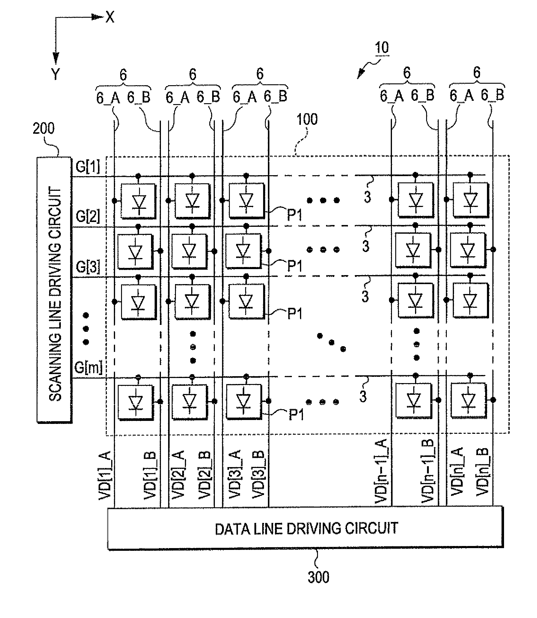
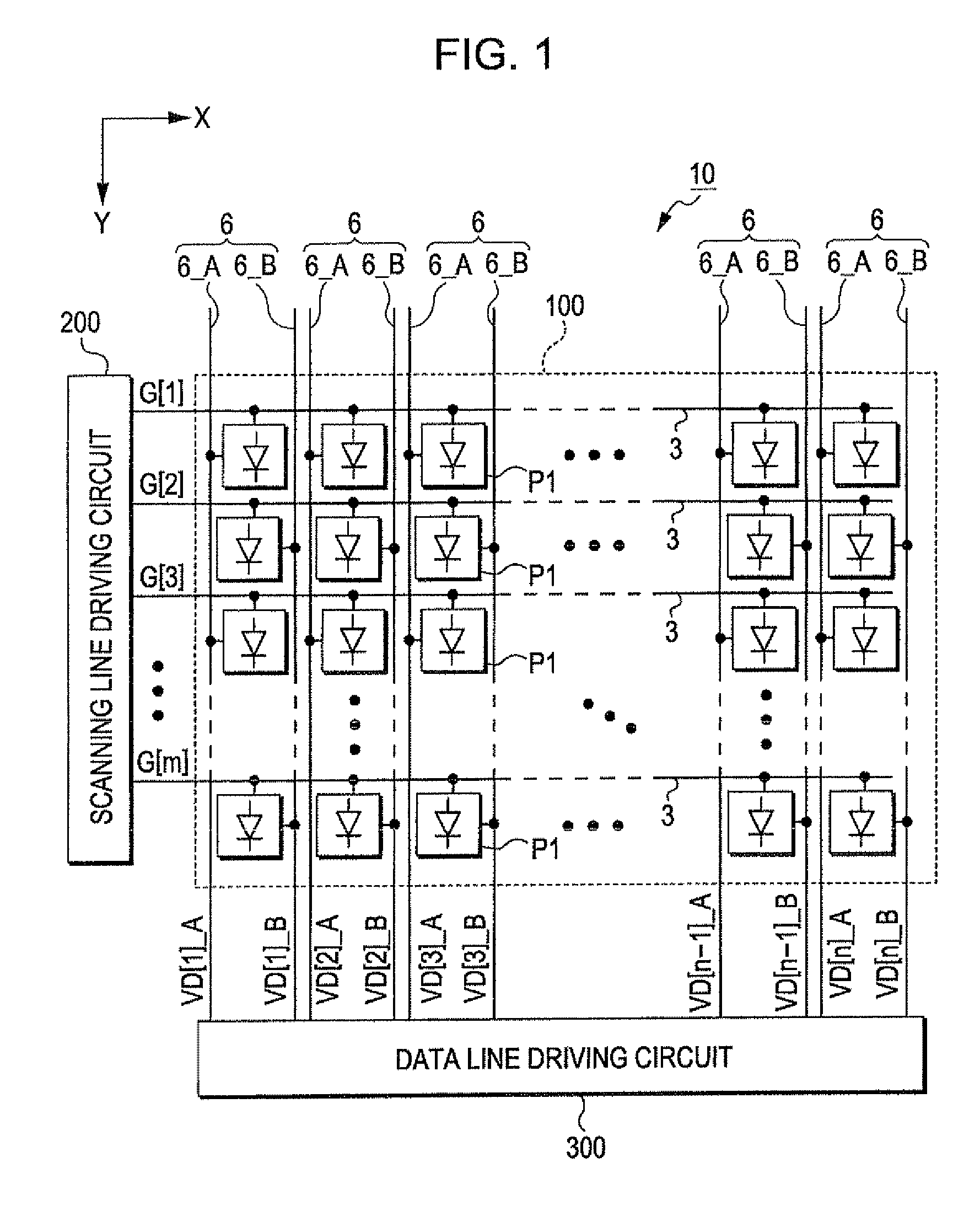
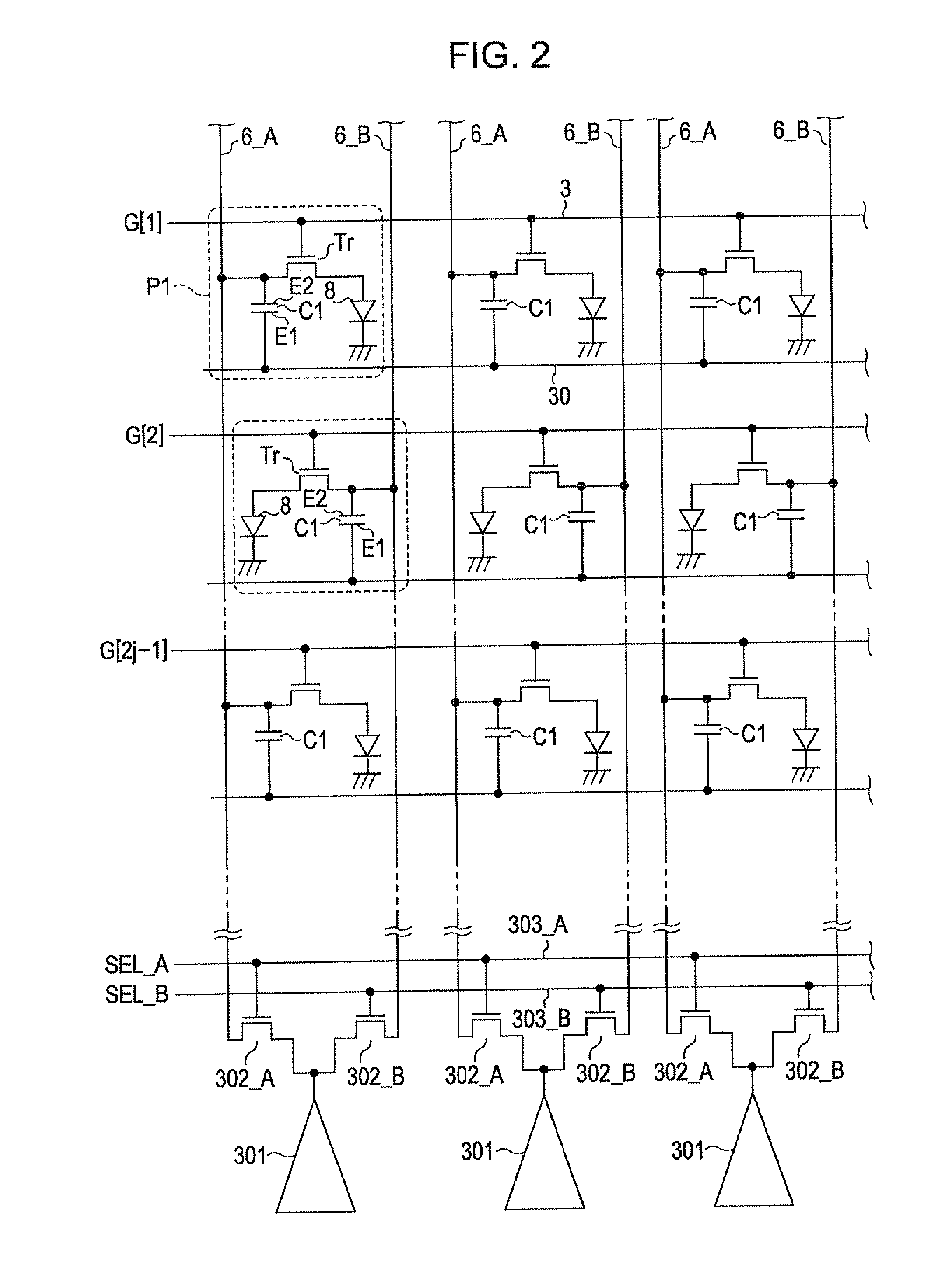
[0071]Hereinafter, a first embodiment according to the invention will be described with reference to FIGS. 1 and 2. In each drawing which will be referred to hereinafter, ratios of the sizes of respective parts may be different from those of real sizes.

[0072]In FIG. 1, an electro-optical apparatus 10 is an apparatus which is applied to a variety of electronic devices for displaying images, and includes a pixel array unit 100 in which a plurality of unit circuits P1 is arranged in a planar shape, a scanning line driving circuit 200 and a data line driving circuit 300. In FIG. 1, the scanning line driving circuit 200 and the data line driving circuit 300 are illustrated as separate circuits, but a part or all of these circuits may be configured as a single circuit.

[0073]As shown in FIG. 1, m scanning lines 3 which are extended in an X direction and n data lines 6 which are extended in a Y direction perpendicular to the X direction are installed in the pixel array unit 100 (m and n are...

second embodiment

[0112]Hereinafter, a second embodiment according to the invention will be described with reference to FIGS. 8 and 9. The second embodiment has a characteristic that data electric potential generating units for respective wirings 6_A and 6_B included in each data line 6 are provided. Other configurations and operations or actions of the second embodiment are the same as those of the first embodiment. Accordingly, hereinafter, the difference will be mainly described and other description will be appropriately simplified or omitted.

[0113]In the second embodiment, as shown in FIG. 8, a data line driving circuit 300 includes two sections which are separated up and down in the figure. That is, the data line driving circuit 300 includes a plurality of data electric potential generating units 304_A connected to the respective wirings 6_A in the lower side in FIG. 8, and a plurality of data electric potential generating units 304_B connected to respective wirings 6_B in the upper side in FIG...


PUM


Abstract

A electro-optical apparatus includes: a plurality of unit circuits arranged to correspond to intersections of scanning lines and data lines; a scanning line driving circuit; and a data line driving circuit. Each unit circuit includes: an electro-optical element which provides gradation corresponding to the data electric potential; a capacitor element which has a first electrode connected to a capacitor line and a second electrode connected to the data line; and a switching element. A second electrode of the capacitor element included in one of the plurality of unit circuits is connected to one wiring of the respective wirings included in the data line. The second electrode of the capacitor element included in another unit circuit is arranged in parallel with the one unit circuit along an extension direction of the data line and is connected to another wiring of the respective wirings included in the data line.

Description

BACKGROUND[0001]1. Technical Field[0002]The present invention relates to an electro-optical apparatus including an organic EL (electro luminescent) element, a liquid crystal or the like, a driving method thereof and an electronic device.[0003]2. Related Art[0004]An electro-optical apparatus including an organic EL element or the like as an electro-optical element is provided in the related art. In the electro-optical apparatus, a variety of driving circuits is provided for supplying a predetermined electric current or voltage to the organic EL element or the like. Such a driving circuit may include, for example, a capacitor element which is connected in parallel with the organic EL element, in addition to the organic EL element. In this case, a data electric potential is supplied to a positive electrode of the organic EL element and one electrode of the capacitor element, and a reference electric potential is supplied to a negative electrode of the organic EL element and the other e...

Claims


Application Information

Patent Timeline
IPC IPC(8): G09G5/10
CPCG09G3/3258G09G3/3291G09G3/3688G09G2310/0297G09G2310/0218G09G3/3225G09G2310/0216
Inventor KASAI, TOSHIYUKI
Owner SEIKO EPSON CORP
Learn More