
Hydraulic setting assembly

Active Publication Date: 2010-10-07
SCHLUMBERGER TECH CORP
View PDF82 Cites 92 Cited by
  • Summary
  • Abstract
  • Description
  • Claims
  • Application Information

AI Technical Summary

Benefits of technology

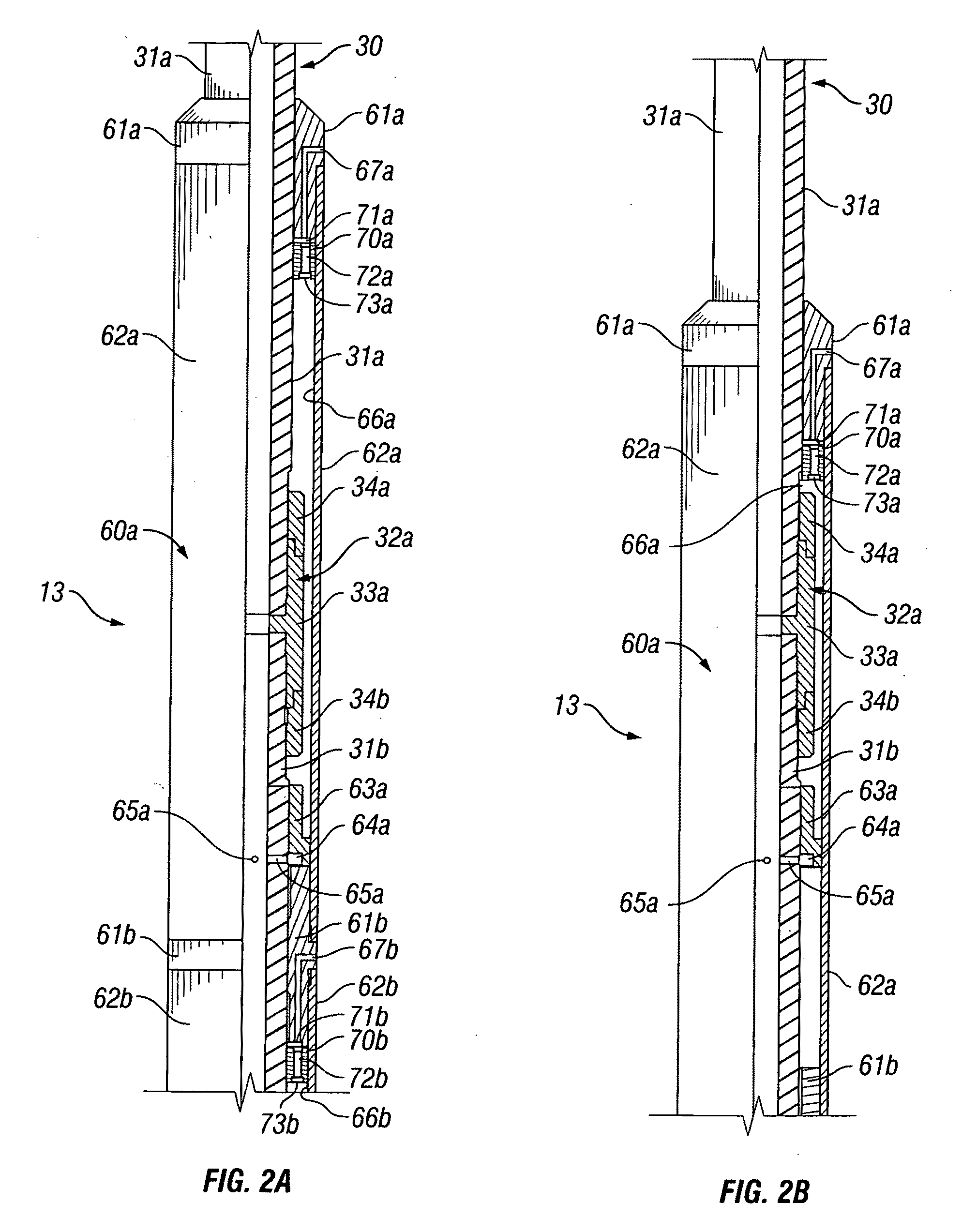
[0030]The novel actuators further include a balance piston. The balance piston is slidably supported within the top hydraulic chamber of the actuator, preferably on the mandrel. The balance piston includes a passageway extending axially through the balance piston. Fluid communication through the piston and between its upper and lower sides is controlled by a normally shut valve in the passageway. Thus, in the absence of relative movement between the mandrel and the cylinder, the balance piston is able to slide in response to a difference in hydrostatic pressure between the outlet port, which is on one side of the balance piston, and the portion of the top hydraulic chamber that is on the bottom side of the balance piston. The novel actuators, therefore, are less susceptible to damage caused by differences in the hydrostatic pressure inside and outside of the actuator. Moreover, the balance piston of the novel actuators is able to prevent the ingress of debris into the actuator.
[0034]The novel anchor assemblies preferably have a load capacity of at least 100,000 lbs, more preferably, a load capacity of at least 250,000 lbs, and most preferably a load capacity of at least 500,000 lbs. The novel anchors thus are able to support the weight of liners and other relative heavy downhole tools and well components.
[0036]As will become more apparent from the detailed description that follows, once the sleeve is expanded, the mandrel and swage provide radial support for the sleeve, thereby enhancing the load capacity of the novel anchors. Conversely, by enhancing the radial support for the sleeve, the novel anchors may achieve, as compared to expandable liners, equivalent load capacities with a shorter sleeve, thus reducing the amount of force required to set the novel anchors. Moreover, unlike expandable liners, the mandrel of the novel anchor assemblies is substantially nondeformable and may be made from harder, stronger, more corrosion resistant metals.
[0037]In yet other aspects the subject invention provides for novel clutch mechanisms which may be and preferably are used in the mandrel of the novel anchor and tool assemblies and in other sectioned conduits and shafts used to transmit torque. They comprise shaft sections having threads, on the ends to be joined and prismatic outer surfaces adjacent to their threaded ends. A threaded connector joins the threaded ends of the shaft sections. The connector has axial splines. A pair of clutch collars is slidably supported on the prismatic outer surfaces of the shaft sections. The clutch collars have prismatic inner surfaces that engage the prismatic outer surfaces of the shaft sections and axial splines that engage the axial splines on the threaded connector. Preferably, the novel clutch mechanisms also comprise recesses adjacent to the mating prismatic surfaces that allow limited rotation of the clutch collars on the prismatic shaft sections to facilitate engagement and disengagement of the mating prismatic surfaces. Thus, as will become more apparent from the detailed description that follows, the novel clutch mechanisms provide reliable transmission of large amounts of torque through sectioned conduits and other drive shafts without damaging the threaded connections.

Problems solved by technology

This simplified drilling process, however, is rarely possible in the real world.
Also, as a well is drilled deeper, especially if it is passing through previously depleted reservoirs or formations of differing porosities and pressures, it becomes progressively harder to control production throughout the entire depth of the borehole.
A drilling fluid that would balance the hydrostatic pressure in a formation at one depth might be too heavy or light for a formation at another depth.
Portions of existing casing also may fail and may need to be patched by installing liners within damaged sections of the casing.
In practice, however, the wedges, cones, and the like that are intended to grip the existing casing may partially extend as the tool is run through existing casing and can cause the hanger to get stuck.
They also may break off and interfere with other tools already in the well or make it difficult to run other tools through the casing at a later time.
Nevertheless, they suffer from significant drawbacks
First, because part of it must be expandable, the liner is necessarily is fabricated from relatively ductile metals.
Such metals typically have lower yield strengths, thus limiting the amount of weight and, thereby, the length of liner that may be supported in the existing casing.
Shorter liner lengths, in deeper wells, may require the installation of more liner sections, and thus, significantly greater installation costs.
This problem is only exacerbated by the fact that expansion creates a weakened area between the expanded portion and the unexpanded portion of the liner.
This weakened area is a potential failure area which can damage the integrity of the liner.
Second, it generally is necessary to expand the liner over a relatively long portion in order to generate the necessary grip on the existing casing.
It can be a significant limiting factor, however, when the expanded liner portion is intended to support long, heavy liners.
Thus, there is progressively more friction between the expanding tool and the liner being expanded and more setting force is required to overcome that increasing friction.
The need for greater setting forces over longer travel paths also can increase the chances that liner will not be completely set.
Thus, it may not be possible to fabricate the liner from more corrosion resistant alloys.
Another reality facing the oil and gas industry is that most of the known shallow reservoirs have been drilled and are rapidly being depleted.
Many operations, such as mounting a liner, can be practiced with some degree of error at relatively shallow depths.
Similarly, the cost of equipment failure is relatively cheap when the, equipment is only a few thousand feet from the surface.
When the well is designed to be 40,000 feet or even deeper, such failures can be costly in both time and expense.
There is a certain irony too in the fact that failures are not only more costly at depth, but that avoiding such failures is also more difficult.
Temperature and pressure conditions at great depths can be extreme, thus compounding the problem of designing and building tools that can be installed and will function reliably and predictably.
Such actuators, however, can be damaged by the hostile environment in which they must operate.
The hydrostatic pressures encountered in a well bore can be extreme and imbalances between the pressure in the mandrel and outside the actuator are commonly encountered.
If the ports are closed while the tool is being run into a well, such pressure differentials will not cause unintended movement of the actuator, but they can impair subsequent operation of the actuator by deforming the actuator cylinder.
Fluids in a well bore, however, typically carry a large amount of gritty, gummy debris.
Nevertheless, the tool may be exposed to wellbore fluid for prolonged periods and under high pressure, and debris still can work its way into conventional actuators and impair their operation.
The rotational forces transmitted through the tool, however, can, be substantial and can damage threaded connections by over-tightening the threads.
In either event, if connections in the torque transmitting components are impaired, it may -be difficult or impossible to operate the tool.
Set screws, pins, keys, and the like, therefore, have been used to secure a connector, but such approaches are susceptible to failure.

Method used


Image

  • Hydraulic setting assembly
  • Hydraulic setting assembly
  • Hydraulic setting assembly

Examples


Embodiment Construction

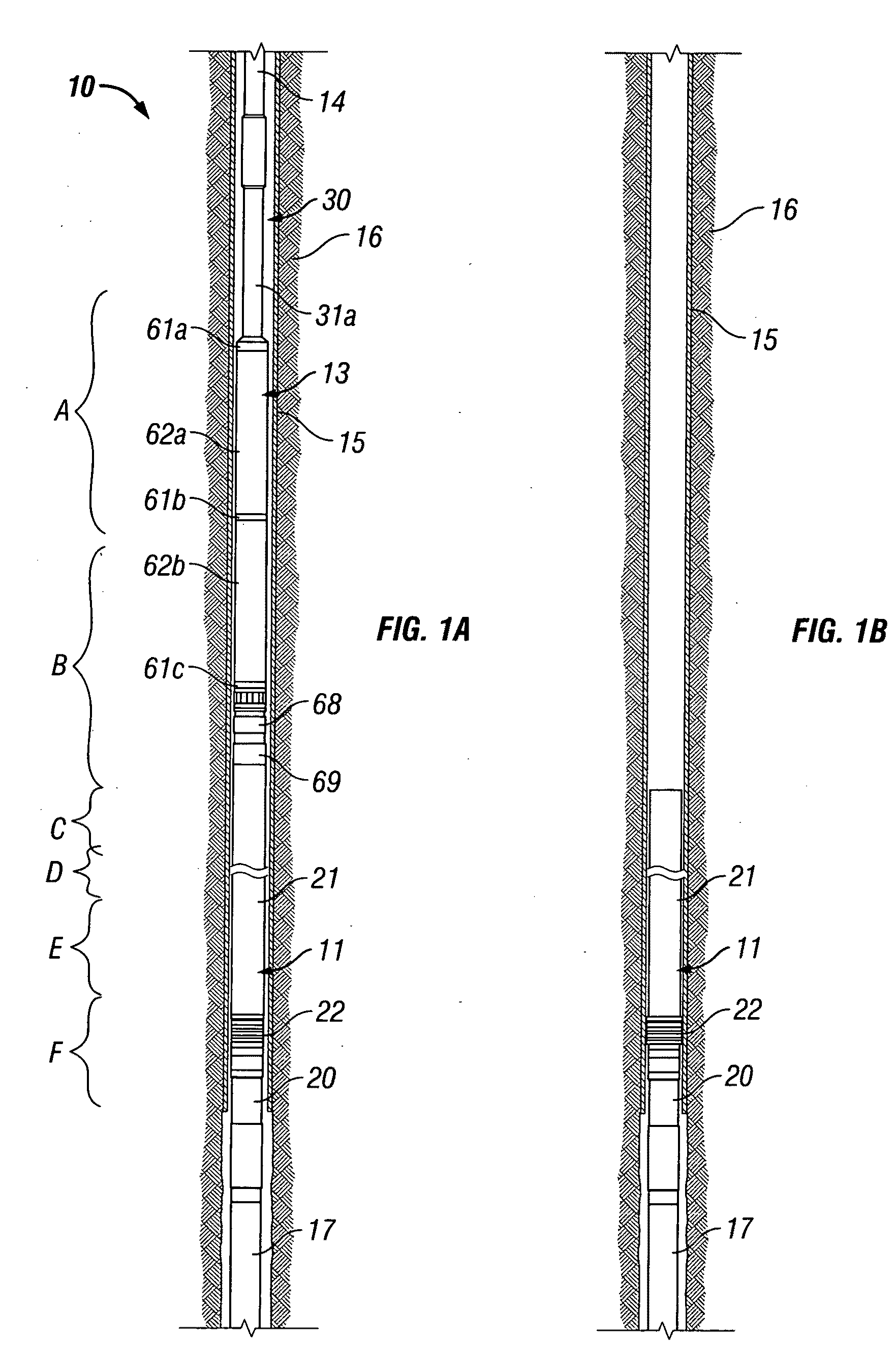
[0060]The anchor assemblies of the subject invention are intended for installation within an existing conduit. They comprise a nondeformable mandrel, an expandable metal sleeve, and a swage. The expandable metal sleeve is carried on the outer surface of the mandrel. The swage is supported for axial movement across the mandrel outer surface from a first position axially proximate to the sleeve to a second position under the sleeve. The movement of the swage from the first position to the second position expands the sleeve radially outward into contact with the existing conduit.

[0061]The novel anchor assemblies are intended to be used in combination with a tool for installing the anchor in a tubular conduit. The anchor and tool assembly comprises the anchor assembly, a running assembly, and a setting assembly. The running assembly releasably engages the anchor assembly. The setting assembly is connected to the running assembly and engages the swage and moves it from its first position...


PUM


Abstract

Novel hydraulic actuators and hydraulic setting assemblies are provided for use in downhole, oil and gas well tools. The novel hydraulic actuators include a cylindrical mandrel and an annular stationary' sealing member connected to the mandrel. A hydraulic cylinder is slidably supported on the mandrel and stationary sealing member and is releasably fixed in position on the mandrel. The stationary sealing member divides the interior of the cylinder into a bottom hydraulic chamber and a top hydraulic chamber. An inlet port provides fluid communication into the bottom hydraulic chamber, and an outlet port provides fluid communication into the top hydraulic chamber. A balance piston is slidably supported within the top hydraulic chamber of the actuator. The piston includes an axially extending passageway. Fluid communication through the piston and between its upper and lower sides is controlled by a normally shut valve in the passageway. In the absence of relative movement between the mandrel and cylinder, the balance piston is able to slide in response to a difference in hydrostatic pressure between the outlet port, is which is on one side of the piston, and the portion of the top hydraulic chamber that is on the bottom side of the piston.

Description

CLAIM TO PRIORITY[0001]This nonprovisional application claims priority of prior nonprovisioinal application of Michael J. Harris and Martin Alfred Stulberg, entitled “Anchor Assembly,” U.S. Ser. No. 12 / 592,026, filed Nov. 19, 2009, and provisional application of Michael J. Harris and Marty Stulberg, entitled “Anchoring Device,” U.S. Ser. No 61 / 166,169, filed Apr. 2, 2009.FIELD OF THE INVENTION[0002]The present invention relates to downhole tools used in oil and gas well drilling operations and, more particularly, to a hydraulic setting assembly which may be used to actuate anchors for well liners and other downhole tools and to tools and methods utilizing the novel hydraulic setting assembly.BACKGROUND OF THE INVENTION[0003]Hydrocarbons, such as oil and gas, may be recovered from various types of subsurface geological formations. The formations typically consist of a porous layer, such as limestone and sands, overlaid by a nonporous layer. Hydrocarbons cannot rise through the nonpor...

Claims


Application Information

Patent Timeline
IPC IPC(8): E21B33/12
CPCE21B23/01E21B23/04E21B43/105E21B33/04E21B43/103E21B23/06E21B23/042
Inventor HARRIS, MICHAEL J.STULBERG, MARTIN ALFRED
Owner SCHLUMBERGER TECH CORP
Learn More