
Computerized method for loading a load carrier with packages

a load carrier and computerized technology, applied in the direction of stacking articles, instruments, de-stacking articles, etc., can solve the problems of difficult calculation implementation and handling, over-building, and not very densely packed

Active Publication Date: 2010-09-30
KUKA ROBOTER
View PDF3 Cites 30 Cited by
  • Summary
  • Abstract
  • Description
  • Claims
  • Application Information

AI Technical Summary

Benefits of technology

[0008]It is therefore the object of the present invention to improve the load of a load carrier with packages, in particular to improve automated loading of the load carrier by a manipulator.
[0012]Such pressures that can be added can be determined on the basis of maximum allowable pressures for packages that can advantageously be determined on the basis of a homogeneously filled or populated, in particular densely or most densely packed, package stack. Allowable or optimal loading patterns are frequently known for homogeneous package stacks or are simple to determine empirically or by calculation. The pressure acting on the lowermost layer as a maximum allowable pressure for packages of the types of the stack can be estimated based on measurements of such a homogeneous package stack, in particular its loading area or the contact area of said lowermost layer, its maximum stack height and its maximum load weight, which enables a particularly simple and reliable determination of a maximum allowable pressure as an initial value for pressures that can be added.
[0016]Particularly in order to protect more sensitive packages, a maximum stack height, empirically or computationally determined for homogeneous package stacks can be reduced to determine the maximum allowable pressure according to the present invention. In this way it is ensured that such packages are not subjected to the pressure occurring in a densely packed, homogeneous stack.

Problems solved by technology

Due to the number of packages to be classified and rules to be mapped, not only is this method complicated and difficult to implement and handle in terms of calculation, but also often lead to more disadvantageous, in particular less overbuilt and not very densely packaged, package stacks in which packages are barely staggered with one another.

Method used


Image

  • Computerized method for loading a load carrier with packages
  • Computerized method for loading a load carrier with packages
  • Computerized method for loading a load carrier with packages

Examples


Embodiment Construction

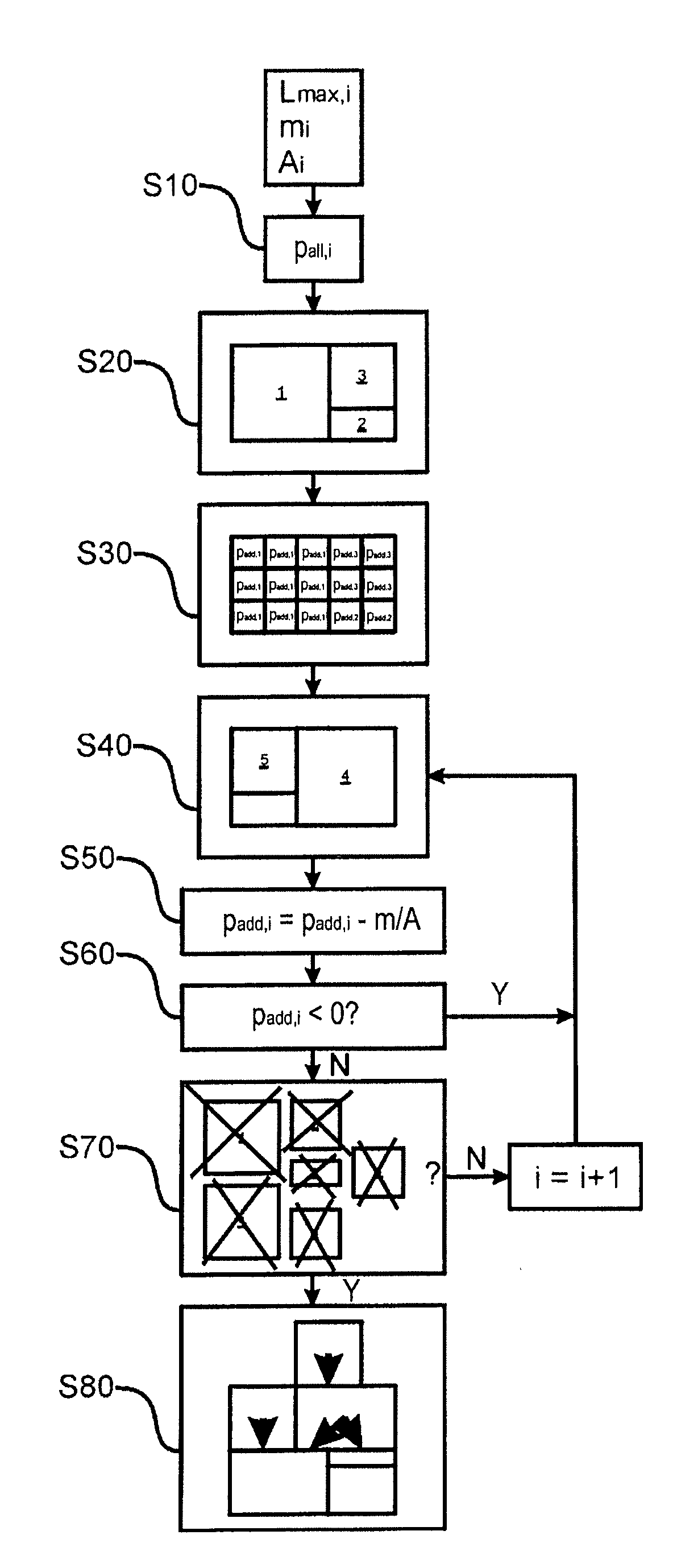
[0029]FIG. 5 shows a flowchart of an iterative generation in a computer (processor) of an allowable package stack composed of 6 packages 1, . . . , 6 according to an embodiment of the present invention, under consideration of maximum allowable pressures on packages. Such a computer can be programmed to execute the steps shown in FIG. 5 by a non-transitory computer-readable medium that is loaded into (stored in) the computer, and that is encoded with programming instructions that cause the computer to execute the steps of FIG. 5.

[0030]First, the maximum allowable pressure pall n that may act on the packages to be consigned is estimated in a first Step S10.

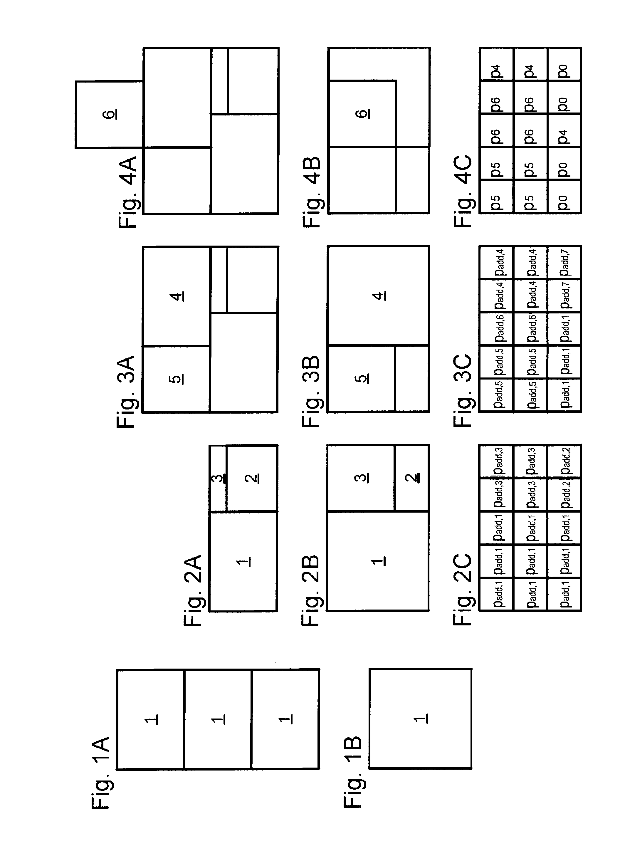
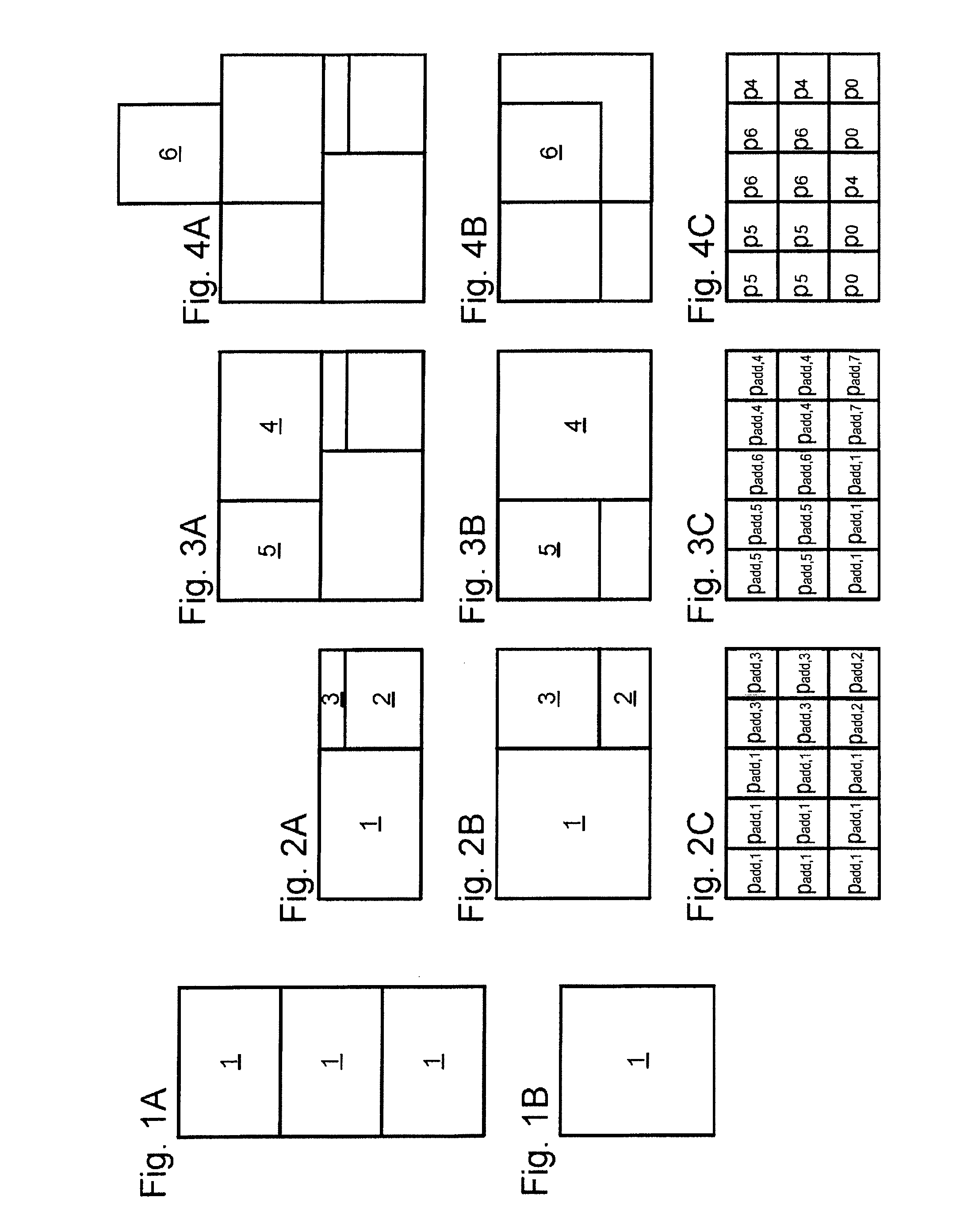
[0031]For this purpose, for each package type a homogeneous pallet of this package type forms the base on which packages are palletized in the densest packing up to a then-maximum allowable stack height. FIGS. 1A, 1B show in side view and plan view from above such a pallet as an example in which identical packages 1 are stacked up t...


PUM


Abstract

In a computerized method, and a computer-readable medium encoded with programming instructions for implementing the method, multiple layers of packages stacked on a load carrier are virtually constructed in a computer and, for each of the layers, an automatic determination is made with regard to the additive pressure that each layer exerts on the respective layers therebelow in the stack. The packages are organized in the multiple layers in the virtual construction dependent on predetermined constraints for the respective additive pressures, and the virtual construction is made available at an output of the computer in a form allowing the actual loading of the load carrier with the packages to be guided.

Description

BACKGROUND OF THE INVENTION[0001]1. Field of the Invention[0002]The present invention concerns a method and a device for planning the automated loading of a load carrier (in particular a pallet) with packages.[0003]2. Description of the Prior Art[0004]For example, an automated planning of a palletizing or loading pattern (i.e. an arrangement of packages on a load carrier) is known from EP 1 211 203 B1. “Packages” as used herein designates individual goods or goods bundles in general, in particular those transported by manipulators.[0005]DE 10 2007 001 263 A1 discloses a method for checking such palletizing patterns with regard to the stability of the package stack, i.e. the packages arranged on the load carrier, by constructing virtual package layers and determining characteristic values for these virtual package layers.[0006]In order to avoid damaging packages and a collapse of the package stack, it is known in practice to classify the packages that are to be placed into ranking cl...

Claims


Application Information

Patent Timeline
IPC IPC(8): G06F7/00G06Q10/00
CPCB65G57/00G06F17/5018G06Q10/08B65G61/00G06F30/23
Inventor BALDES, LARSRUGE, GERDAHASELMAYR, JULIAN
Owner KUKA ROBOTER
Learn More