
Tracheobronchial pulmonary cryogenic therapeutic method and apparatus

Inactive Publication Date: 2010-09-30
JOHNSTON MARK H
View PDF2 Cites 16 Cited by
  • Summary
  • Abstract
  • Description
  • Claims
  • Application Information

AI Technical Summary

Benefits of technology

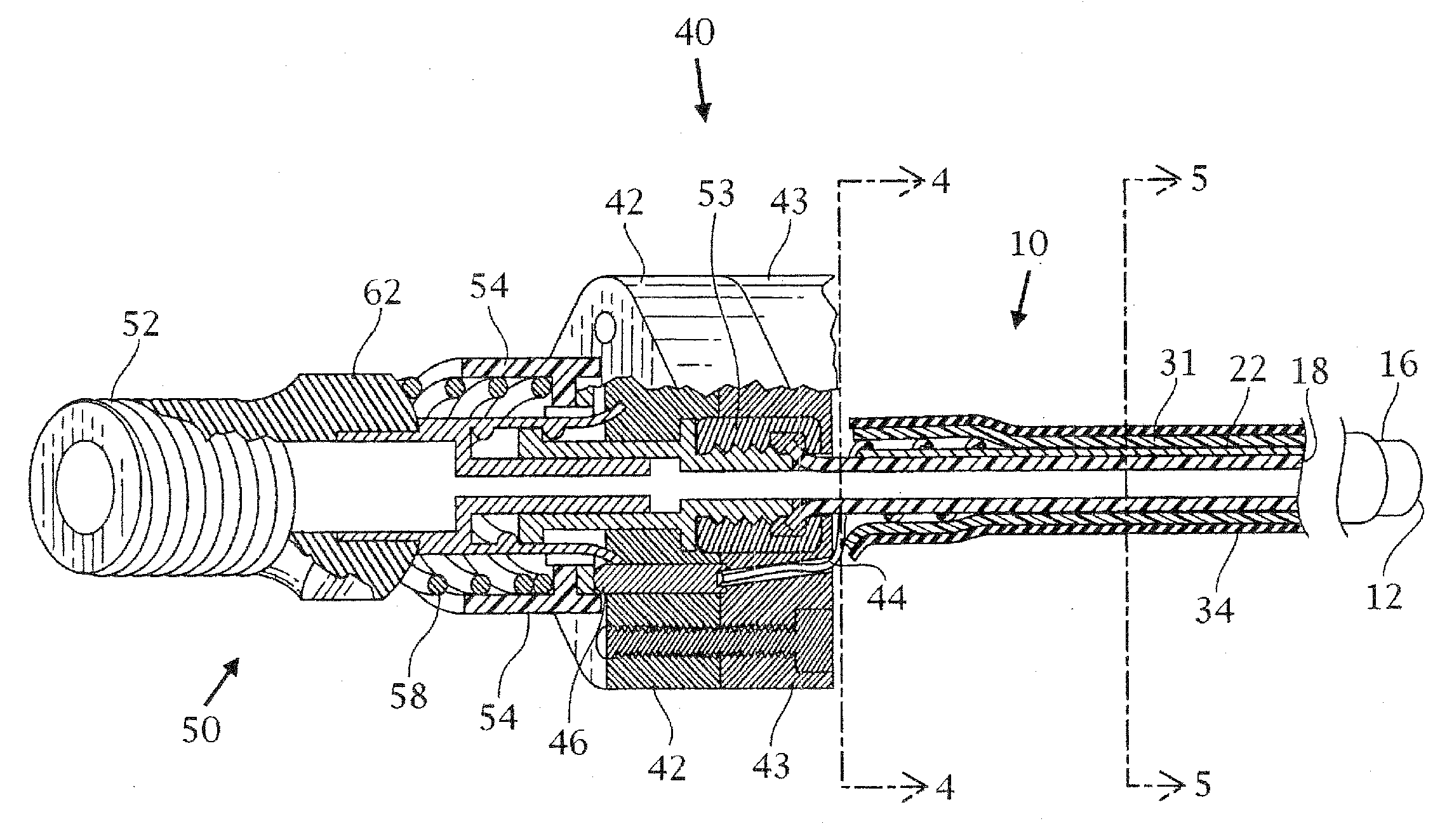
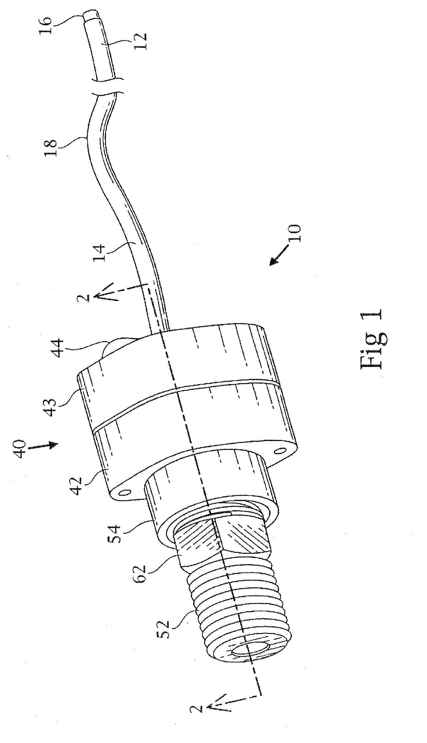
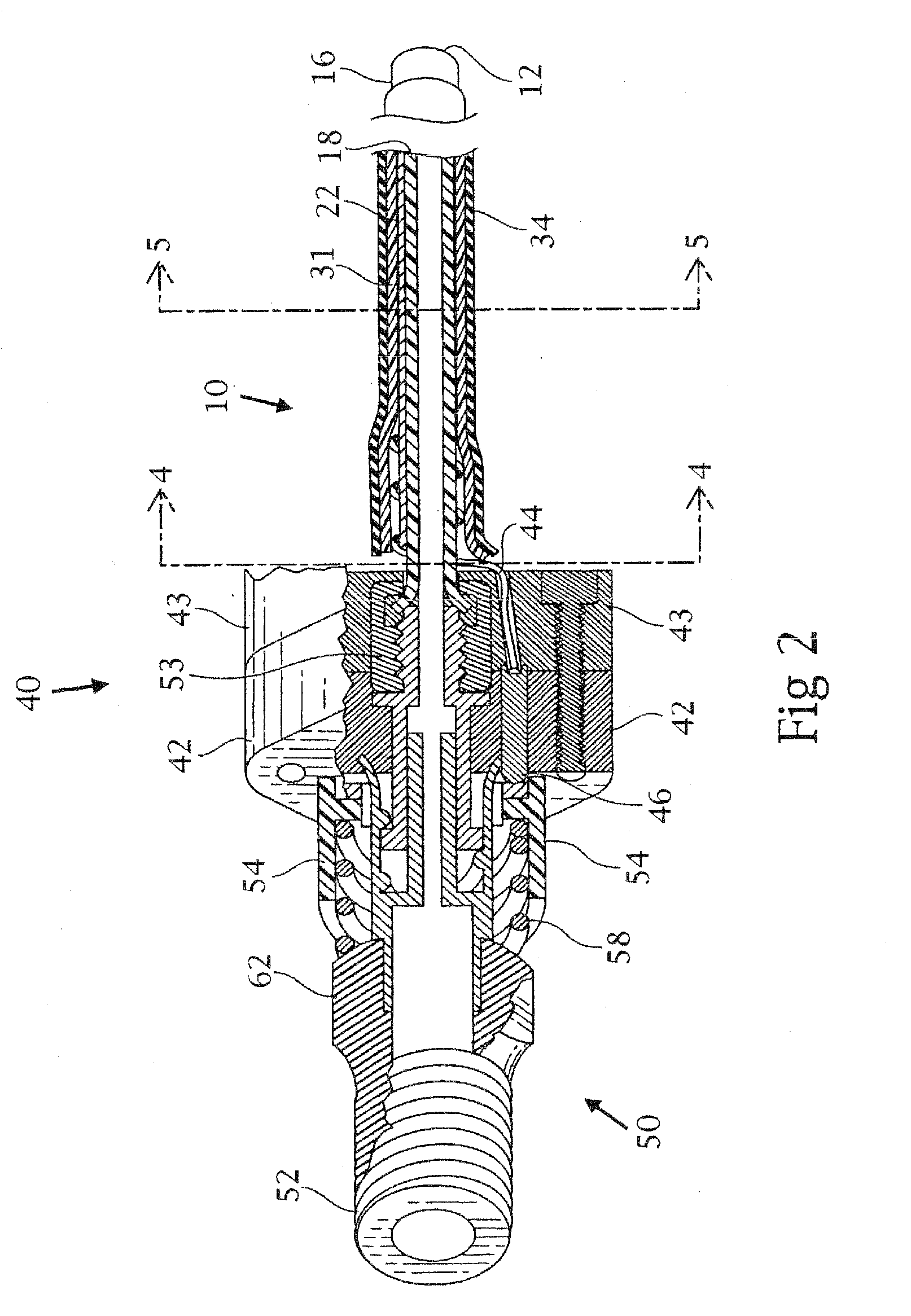
[0017]A completely automated system with sensors and a microprocessor are employed for performing cryosurgery. It is an important preferred feature of the present invention that the spray be conducted in such a manner as to allow constant visualization by the physician of the tissue treatment as it occurs. If the temperature of the lens at the distal end of the endoscope drops precipitously at the start of the liquid nitrogen spray, the moist air of the esophageal environment or tracheal environment or the air of the catheter which has been blown out ahead of the nitrogen flow will condense on the lens, thereby obscuring the physician's view of the operative site. This can be substantially avoided by means of a suction pump which will immediately suck out the moist air which is present prior to the arrival of the liquid nitrogen spray or cold nitrogen gas. Because of this pumping out of the moist air as the spray commences and the replacement with extremely dry nitrogen gas, substantial amounts of moisture will not form on the lens during the procedure, allowing an excellent view of the operative site by the physician during the procedure.
[0041]A bleeder valve is not absolutely essential to this invention since low pressure cryoablation can be carried out through low head pressure in the storage tank or through selection of the proper inner diameter of the catheter. Based on studies carried out with the bleeder valve embodiment a shorter time period is required for cryoburn.

Problems solved by technology

It is reported therein that the cold cryogenic gas tends to make the catheter stiff and unmanageable, and at times rupturing the catheter.

Method used


Image

  • Tracheobronchial pulmonary cryogenic therapeutic method and apparatus
  • Tracheobronchial pulmonary cryogenic therapeutic method and apparatus
  • Tracheobronchial pulmonary cryogenic therapeutic method and apparatus

Examples


example 1

Pulmonary Cryospray Ablation for Treatment of Benign Airway Disease

[0109]The cryospray was used in the present studies to demonstrate the utility of the present invention for use in the treatment of lesions of the tracheobronchial system. In particular, the present example demonstrates the utility of the present invention for treatment of benign airway disease (BAD) of the lung using liquid nitrogen sprayed through a catheter via a flexible fiber optic bronchoscopy (FFB).

[0110]The present study will identify an effectiveness endpoint as an improvement in luminal patency following cryospray treatment along with visual confirmation of an absence of scarring and stricturing of the airway. If after the initial repeat bronchoscopy, it is determined that there is no immediate need for further intervention, then any future bronchoscopy will be performed upon the patient presenting with symptoms.

[0111]The cryospray ablation system will be used in the present studies. This system is a cryosu...

example 2

Interventional Cryotherapy in the Pleural Space

[0122]The present example demonstrates the utility of cryospray ablation to treat neoplastic lesions on the parietal pleural surface. Condition: Primary malignancy with metastasis to the parietal pleura pleural surface neoplasms; Intervention: Device: cryospray ablation system.

[0123]Primary Outcome Measures: To reduce tumor burden in the pleural space, as determined by visual inspection and biopsy of the treatment sites 2-5 days post treatment. Safety endpoint clinical and radiographic status at 30 days post cryospray treatment and adverse events. Secondary Outcome Measures: To determine if cryospray causes a pleurodesis effect. To determine if cryospray affects production of malignant effusion within the treated pleural cavity. To determine if pleural cavity treatment with cryospray is dosimetry dependent. Intervention Details: Device: Cryospray Ablation System.

[0124]Subjects will be treated with CryoSpray therapy at Day 0 using up to ...

example 3

CryoSpray Abalation in Malignant Airway Disease

[0130]The present example demonstrates the utility of CryoSpray Ablation “CSA” or “cryospray therapy” to treat malignant airway disease in lung using liquid nitrogen sprayed through a catheter via flexible fiber optic bronchoscopy (FFB). The conditions that may be treated according to the present methods include lung cancer, mesothelioma, and malignant airway obstruction, among others.

[0131]Measures: Efficacy of the cryogen on a tumor evaluated by histopathological data and visual inspection along with visual confirmation of absence of scarring and stricturing of the airway. The primary safety endpoint is the reporting of all adverse events. Designated as safety issue: Yes Secondary Outcome Measures: Consists of a measure of treatment efficacy and improvement in luminal patency assessed by visual inspection. Treatment dosimetry will be up to 4, 5-second spray cycles. Subjects will have initial cryospray treatment at Day 0. Subjects will...


PUM


Abstract

Disclosed are methods for the cryoablation treatment of a patients tracheobronchial pulmonary system, such as in the treatment of tracheobronchial lesions and lung cancer. The pulmonary system treatment method employs a specially dimensioned dorsal end catheter system that includes a proximal end suitable to provide for the delivery of a cryogenic material to a desired pulmonary area of interest in a patient. The apparatus includes as a part thereof an endoscope dimensioned so as to be suitable for insertion through a patient's trachea. Provided are tracheobronchial cryoablation methods for treatment of benign airway disease, early lung cancer, sarcoidosis, Wegner's granulomatosis, rhinoscleroma, recurrent respiratory papillomatosis (RRP), benign tracheal stenosis, pulmonary dysplasia, neoplasia, vascular lesions, inflammatory lesions and pulmonary and / or tracheal degenerative lesions.

Description

FIELD OF INVENTION[0001]The invention finds applicability in the filed of cryosurgery where a catheter is used to convey a cryogas to ablate tissue. In particular, the invention finds applicability in the field of cryosurgery in pulmonary tissue and in particular, tracheobronchial tissue.BACKGROUND OF THE INVENTION[0002]Cryospray ablation (CSA) is a tool that has been used in a method for freezing diseased tissue. Upon freezing, the tissue evokes tissue necrosis, allowing the regeneration of healthy tissue.[0003]Cryoablation has been described for use in the treatment of gastrointestinal disease. For example, a method for ablation of tissue in the esophagus using a cryogenic gas is described with the use of a specially designed cryosurgical apparatus for gastrointestinal applications in U.S. Pat. No. 7,025,762. The device includes, in some aspects, an inflating means which aids in preventing gas escape of cryogen into the stomach. The device is described as part of a method used in ...

Claims


Application Information

Patent Timeline
IPC IPC(8): A61B18/02
CPCA61B18/0218A61B2018/0212A61B19/5212A61B19/5202A61B90/30A61B90/361
Inventor JOHNSTON, MARK H.
Owner JOHNSTON MARK H
Learn More