
Blackbody fitting for temperature determination

a technology of blackbody and temperature, applied in the direction of optical radiation measurement, instruments, spectrometry/spectrophotometry/monochromators, etc., can solve the problems of inability to use contact-based thermometry in these situations, and inability to meet the requirements of high-tech manufacturing processes. achieve the effect of simple, straightforward and robust self-calibration techniques

Active Publication Date: 2010-09-30
K SPACE ASSOCS
View PDF26 Cites 27 Cited by
  • Summary
  • Abstract
  • Description
  • Claims
  • Application Information

AI Technical Summary

Benefits of technology

[0025]According to this method, relatively simple, straightforward, and robust self-calibration techniques can be employed by effectively “free fitting” the first acquired spectra in such a way that it takes into account any emissivity variations over time. This self-calibrating technique allows application of fairly standard fitting routines to obtain the best possible fit of the acquired data to an ideal blackbody spectral radiance curve.

Problems solved by technology

However, use of contact-based measurement techniques is often impractical.
It is not feasible to use contact-based thermometry in these situations either, even though the quality of the manufacturing process depends upon temperatures being held to tight tolerances.
Such standard pyrometry techniques prove inadequate to address many of today's highly sophisticated manufacturing processes that require consideration for stray light, emissivity changes during deposition, viewport coating buildups, and the like.
A particular drawback in the concept described in this patent is its functional dependence on the emissivity of the sample being measured.
This dependence on emissivity has the practical effect of introducing measurement errors.
This is an exceedingly complicated approach which is cumbersome and likely to introduce substantial errors in the temperature measurement process.
This, as with the other prior art systems, creates difficulties in real world applications of the technology.
One such shortcoming is a general failure to adequately address variations in spectrometer response with wavelength.
That is, prior art systems fail to adequately correct for variations in the spectrometer that may be present across the entire spectra such as, for example, due to the inherent response of the optical components.
Thus, the pyrometry and blackbody fitting techniques of the prior art are not self-sufficient as a means for determining sample temperature, but rather must be paired with another type of measurement system for at least an initial calibration phase.
This, of course, increases the cost and complexity of manufacturing processes that need thermometry data for proper operation.
Also, this initial calibration step usually requires elevating the sample temperature to a high level, introducing time delay and reducing efficiencies in the manufacturing processes.

Method used


Image

  • Blackbody fitting for temperature determination
  • Blackbody fitting for temperature determination
  • Blackbody fitting for temperature determination

Examples


Embodiment Construction

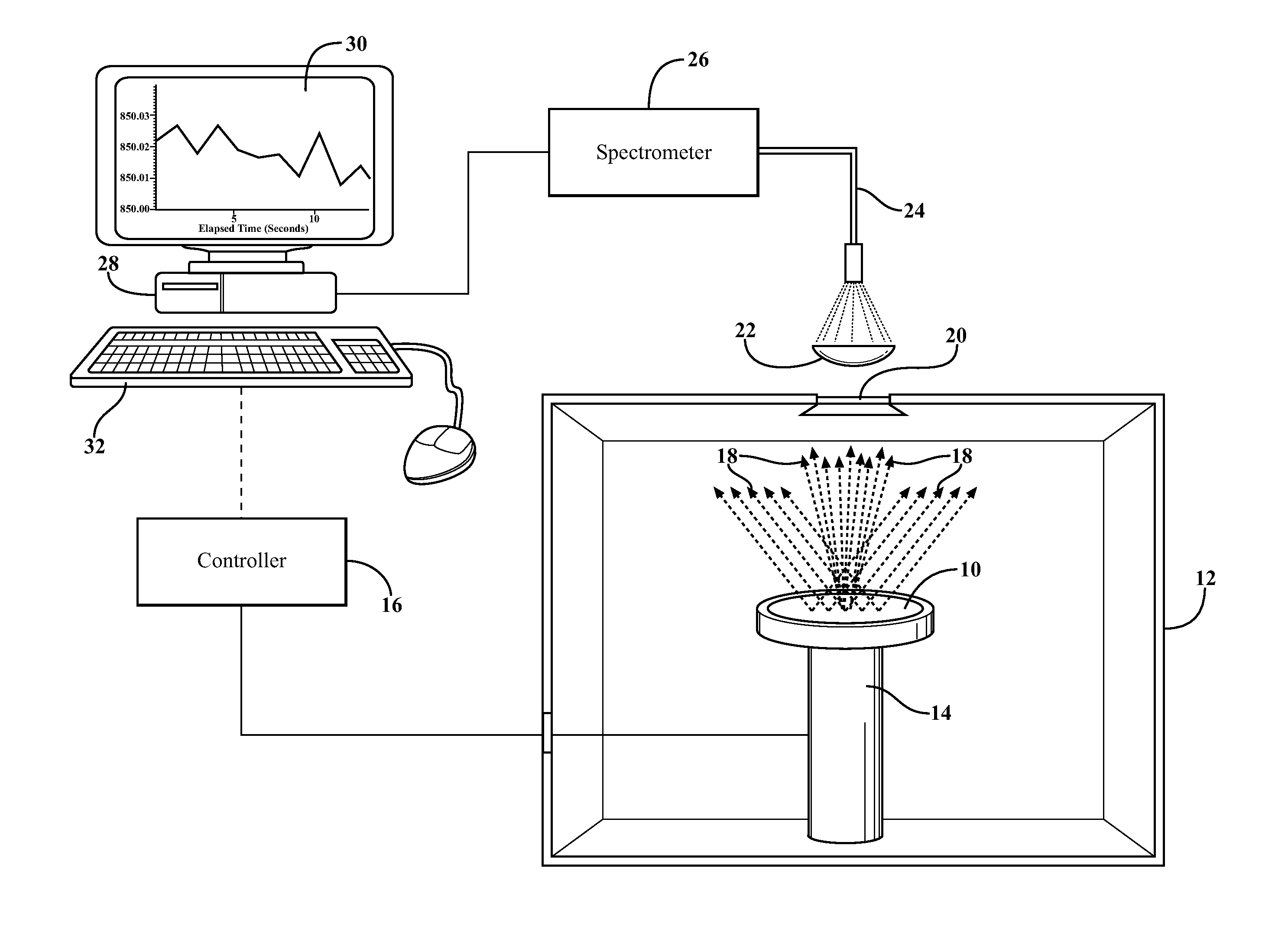
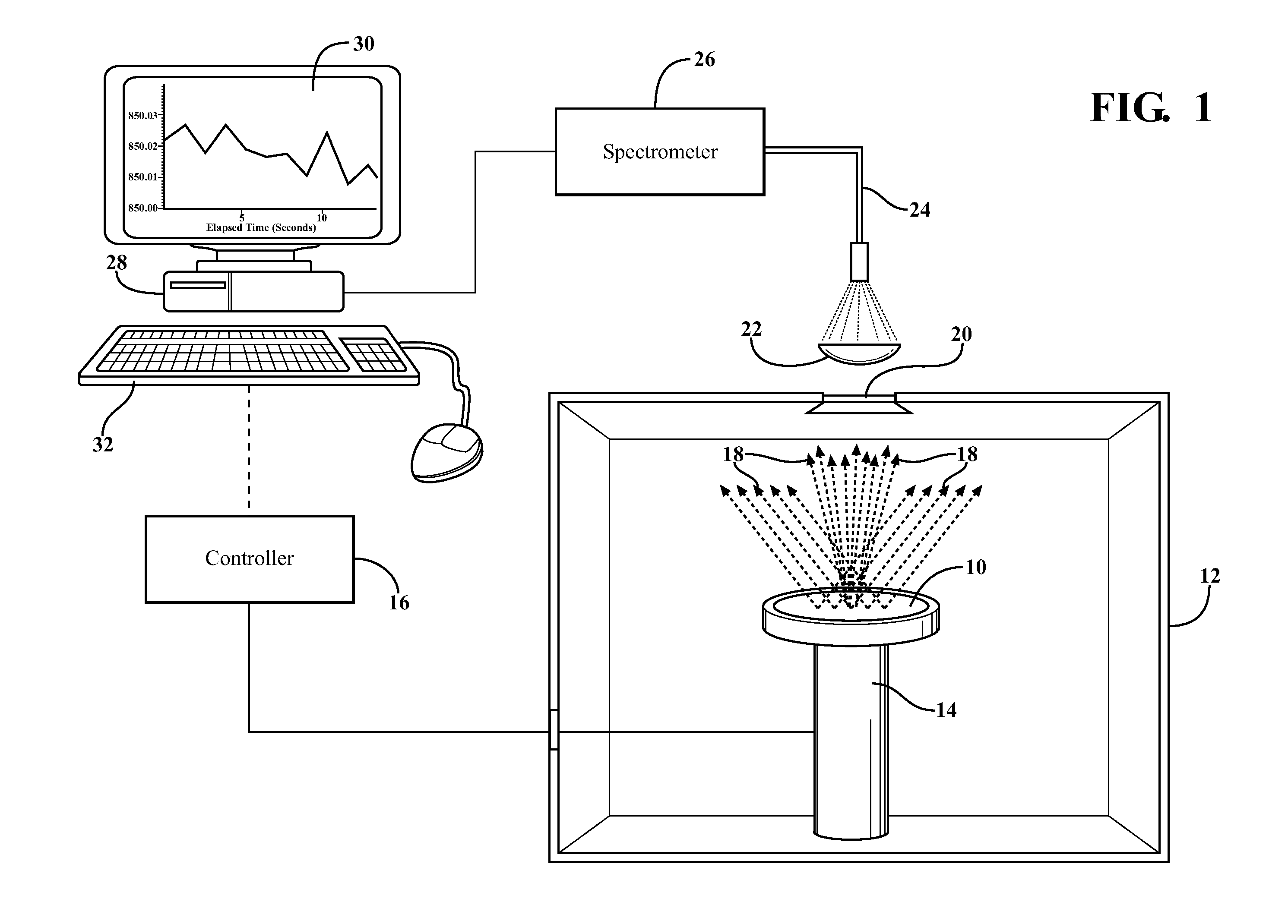
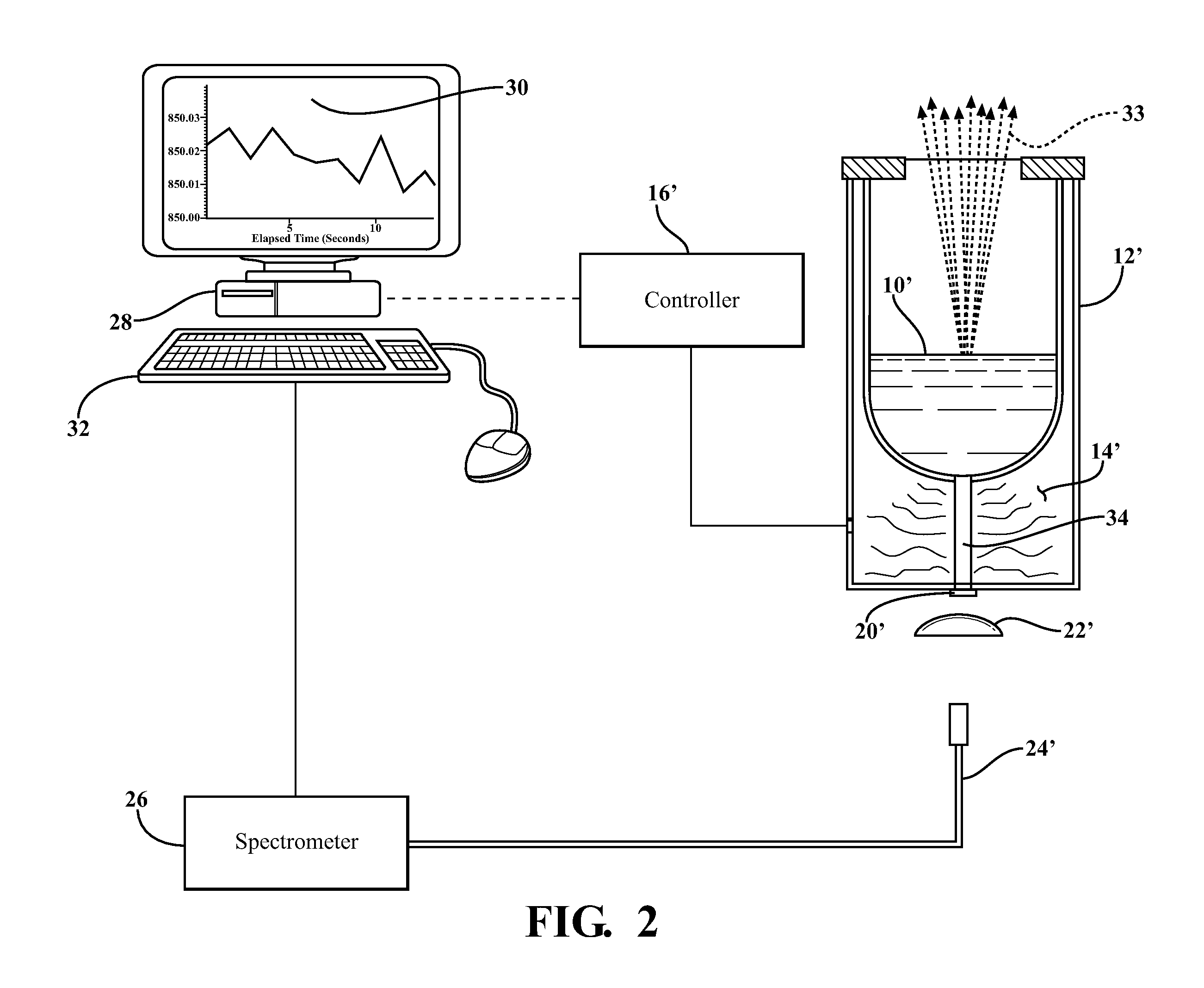
[0038]Referring to the figures wherein like numerals indicate like or corresponding parts throughout the several views, an exemplary application of the subject invention is illustrated schematically in FIG. 1 within the context of a thin film deposition process. In this case, the sample 10 may comprise a thin film substrate or wafer of the type used to manufacture semiconductors. The sample 10 is located within a deposition chamber 12. The sample 10 is associated with a heater 14 capable of being switched on and off by a controller 16 so as to elevate the sample 10 to an appropriate processing temperature and then maintain the sample 10 at a desired temperature throughout the deposition process. The heated wafer sample 10 emits radiation depicted by broken arrows 18 which passes through a viewport window 20 to a lens 22. The lens 22 directs the emitted radiation 18 to an optical fiber 24 which is operatively associated with a solid state spectrometer 26. The spectrometer 26 is used ...


PUM

PropertyMeasurementUnit
wavelength rangeaaaaaaaaaa
wavelengthsaaaaaaaaaa

Abstract

A temperature monitoring technique for collecting radiation intensity (blackbody emission) across a broad wavelength range. A solid state spectrometer (26) acquires spectra from a sample (10) in real time and resolves the spectra to a radiation intensity (I) versus wavelength (λ) curve. This curve is fitted to Planck's equation using a non-linear least squares fitting analysis. The system can be configured to self-calibrate and then lock in an amplitude value (A) which is used in subsequent temperature measurements by fitting to the blackbody emission curve. Preferably, the spectrometer (26) is flat field corrected (36) in an initial step to counteract variations in the spectrometer response with wavelength.

Description

CROSS REFERENCE TO RELATED APPLICATIONS[0001]This application claims priority to Provisional Patent Application No. 61 / 162,698, filed Mar. 24, 2009, the entire disclosure of which is hereby incorporated by reference and relied upon.BACKGROUND OF THE INVENTION[0002]1. Field of the Invention[0003]The invention relates generally to methods for making precise non-contact temperature measurements of a sample based on its thermally-emitted radiation, as well as methods for calibrating such a temperature measurement device.[0004]2. Related Art[0005]Many advanced manufacturing processes depend on the ability to control the temperature of a sample with high precision and repeatability. However, use of contact-based measurement techniques is often impractical. As one example, thin film and semiconductor deposition processes used for manufacturing electronic and optical devices require very precise control of substrate temperatures to yield high quality products, but the temperature measuremen...

Claims


Application Information

Patent Timeline
Patent Type & Authority Applications(United States)
IPC IPC(8): G01K15/00G06F19/00
CPCG01J5/02G01J5/026G01J2003/2866G01J5/60G01J5/522G01J5/53
Inventor BARLETT, DARRYLWISSMAN, BARRY D.TAYLOR, II, CHARLES A.
Owner K SPACE ASSOCS
Learn More