Method and apparatus for high-speed unconstrained three-dimensional digitalization

Inactive Publication Date: 2010-09-30
MICROMETRIC VISION TECH
View PDF14 Cites 83 Cited by
  • Summary
  • Abstract
  • Description
  • Claims
  • Application Information

AI Technical Summary

Benefits of technology

[0021]It is an objective of the present invention to provide a method for high-speed digitalization, by employing simple projection patterns, free of coded elements or intensity features, identifying the patterns in image frames, and obtaining 3-D measurements by triangulation thereof in real-time.
[0024]It is still further objective to provide a 3-D imaging system comprising at least a radiation projector, at least an image sensor and computing means, whereby points coordinate and color are obtained from projecting said patterns, in real-time. It is yet a further objective of present invention to provide a 3-D digitalization system suitable comprising inexpensive, widely-available components.

Problems solved by technology

In many practical situations the locator range is insufficient requiring complex planning and careful data integration, which significantly increase operations complexity and cost, preventing digitalization of moving scenes.
Mitigating these factors may lead to either larger and therefore fewer coded elements, which in turn leads to fewer 3-D measurements, or specialized hardware components, which increase system cost and complexity.
The technique is also error prone, particularly in textured and high contrast variance regions, because of reliance on intensity features, which restricts the type of suitable surfaces.
Also, the technique does not have the ability to capture surface color at measured points.
As such, is unable to operate in the presence of color variation or distinct surface features, and therefore, cannot detect any textural information in real-time.
The technique requires continuity assumption and cannot handle broken lines that may appear on more complex geometries.
Also, it does not provide means for obtaining textural data.
Other more complex techniques employ multi-camera configurations, and multi-frame strip matching, on the expense of increased complexity.
One disadvantage of this procedure is that it requires compromise between color frame field-of-view and resolution, because color assignment to data points cannot be achieved on one-to-one relationship basis.
Another disadvantage is that it requires additional frames capture, taken by an additional camera.
As such, due to complexity and limitations, the system is unsuitable for moving scenes or hand-held operations.
This technique is also deficient because of at least two cameras are required and because of the need for external locator to assemble 3-D frames.

Method used


Image

  • Method and apparatus for high-speed unconstrained three-dimensional digitalization
  • Method and apparatus for high-speed unconstrained three-dimensional digitalization
  • Method and apparatus for high-speed unconstrained three-dimensional digitalization

Examples


Embodiment Construction

[0029]The method of the present invention is presented in the context of a system, providing means for digitalization of three-dimensional objects, by obtaining substantial amounts of accurate range coordinates, free of contact, in real-time, illuminating objects surface by multi-line patterns, identifying each pattern, and calculating point coordinates by triangulation.

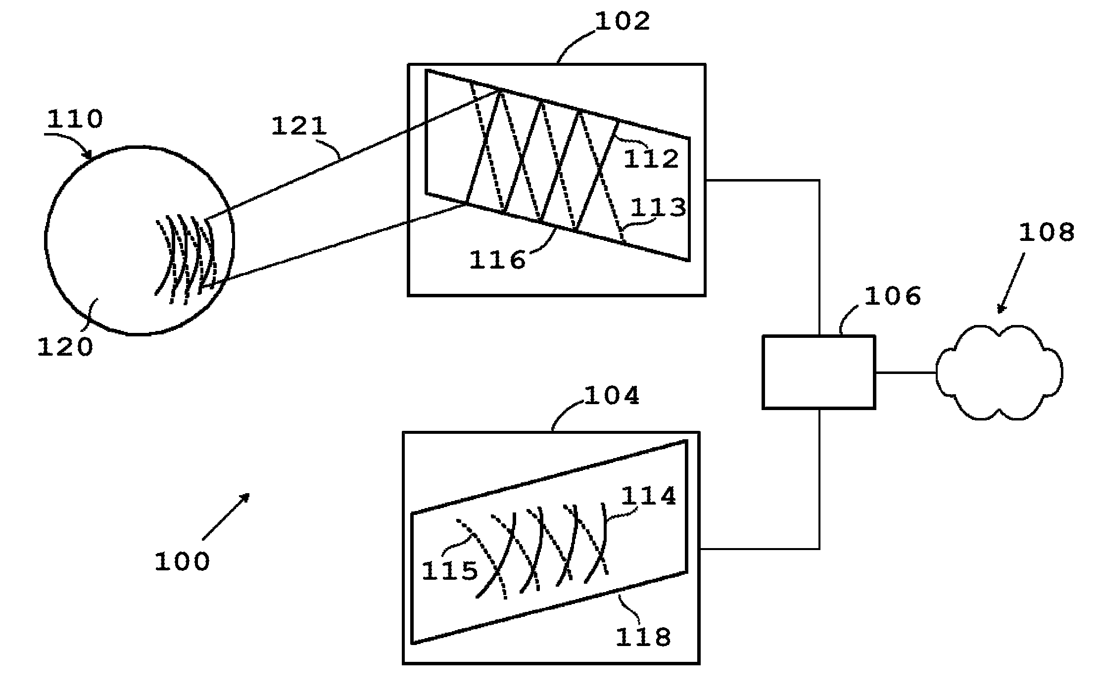
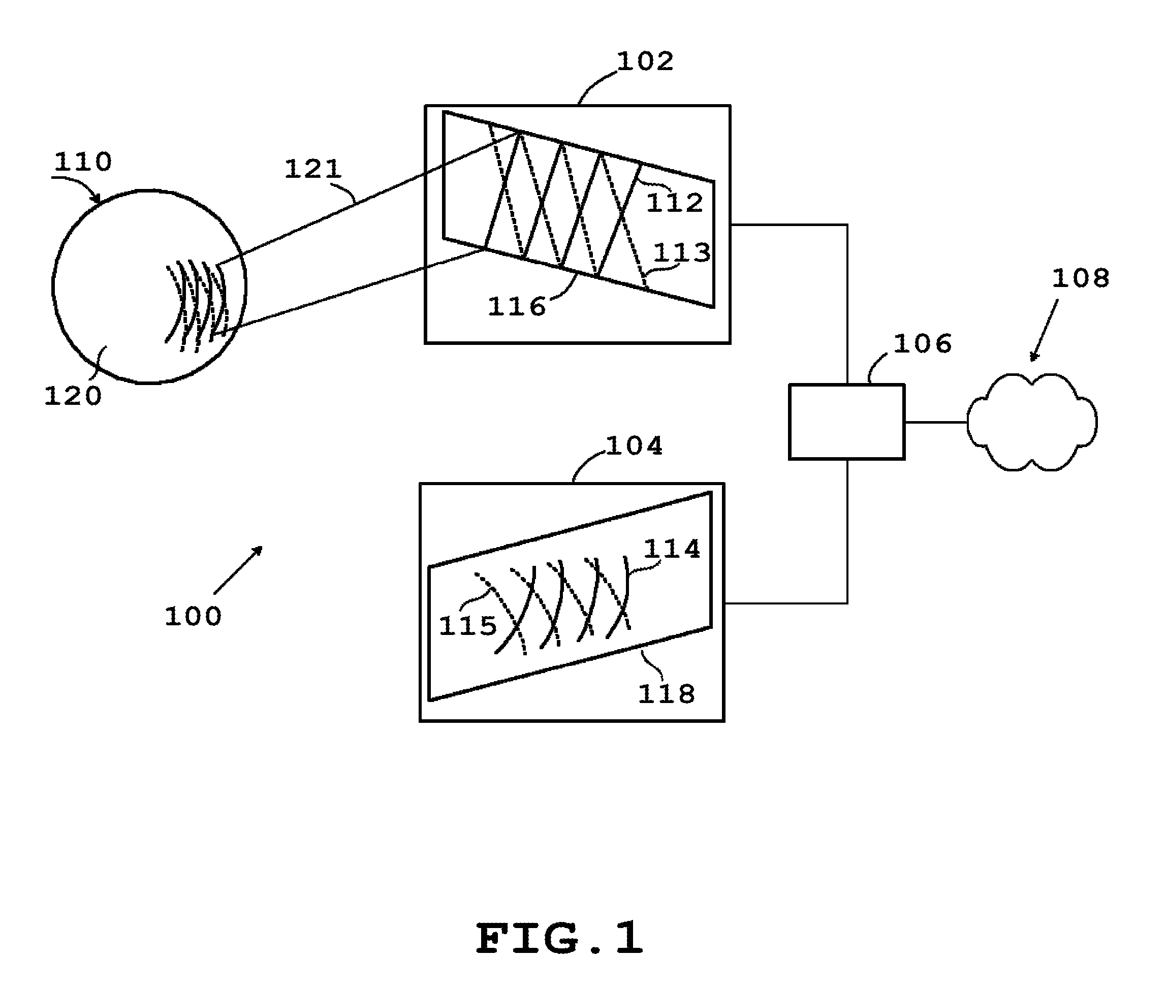
[0030]FIG. 1 is a schematic representation of at least one embodiment of the system of the present invention. The digitizing system 100 consists of a radiation projector 102 and an image detector 104, both coupled to a computer 106. The image detector 104 is fixed relative to projector 102 and positioned at a measurable distance from image detector 104. Projector 102 and detector 104 have a measurable convergent orientation toward object 110.

[0031]Projector 102 radiates a set of patterns, 112 and 113, emanating from plane 116, where pattern strip projections are exemplary represented that solid sheet 121. Image detec...


PUM


Abstract

A method and a system for optical three-dimensional (3-D) digitalization of physical objects, suitable for moving scenes, unattached to locating devices, utilizing structured light in the form of a plurality of overlapped patterns free of any intensity features, capable of obtaining frames of 3-D coordinates and textural color at video frame rates.

Description

PRIORITY[0001]Priority is claimed to Provisional Application No. 61 / 165,077, filed on Mar. 31, 2009DESCRIPTION[0002]1. Field of Invention[0003]The present invention relates to general field of three-dimensional (3-D) optical scanning of objects or scenes, and more particularly to obtaining frames of dense 3D measurements, at rates suitable for moving scenes and hand-held operations, and utilizing simple projection patterns.[0004]2. Background of the Invention[0005]A large number of techniques for obtaining relative distance (range) from imaging device to imaged object have been developed. The devices which obtain the measurements are known as range sensors or 3-D scanners. Range sensors are utilized to capture object shapes with the purpose to create digital representations of 3-D objects in the form of 3-D models, which are commonly used in increasing numbers of scientific and engineering activities. These include documenting artwork, artifact preservation, multimedia, interactive ...

Claims


Application Information

Patent Timeline
IPC IPC(8): G01B11/14
CPCG01B11/2509G01B11/2513G06T7/521G01B2210/52G01B11/2518
Inventor TEODORESCU, NICOLAE
Owner MICROMETRIC VISION TECH
Why Eureka
Try Eureka