
Antenna apparatus

a technology of antenna apparatus and antenna body, which is applied in the direction of antenna details, antenna earthings, antennas, etc., can solve the problems of reducing the gain of the antenna apparatus caused by human approach, and affecting the operation of the antenna apparatus, etc., to achieve low manufacturing cost of the apparatus, high gain, and constant polarized wave ratio

Active Publication Date: 2010-09-30
DENSO CORP +1
View PDF4 Cites 3 Cited by
  • Summary
  • Abstract
  • Description
  • Claims
  • Application Information

AI Technical Summary

Benefits of technology

[0011]In view of the above-described problem, it is an object of the present disclosure to provide an antenna apparatus with a high gain and a low manufacturing cost. The antenna apparatus provides a constant polarized wave ratio without depending on existence of a conductor, which approaches the antenna apparatus.
[0013]In the antenna apparatus, when a conductive object does not approach the apparatus, a combination of the loop antenna and the antenna formed by the substrate provides high gain. Even when the conductive object approaches the apparatus, since emission from the substrate contributes to emission from a whole of the apparatus, the combination of the loop antenna and the antenna formed by the substrate provides high gain.
[0015]When the conductive object approaches the antenna apparatus, the substrate may reduce a function as the antenna. However, since the polarized wave ratio of the loop antenna is equal to the polarized wave ratio of the substrate, the polarized wave ratio of the whole of the apparatus is not changed even when the substrate reduces the function as the antenna, and only the electric field emission from the loop antenna is effective.
[0016]Thus, the polarized wave ratio of the whole of the apparatus is secured without depending on existence of the conductive object. Accordingly, the antenna apparatus has a high gain and a constant polarized wave ratio without depending on existence of the conductive object. Further, since the apparatus is formed easily, a manufacturing cost of the apparatus is low.

Problems solved by technology

Thus, the balance-unbalance conversion circuit prevents the substrate from functioning as an antenna.
Thus, the reduction of gain of the antenna apparatus caused by approach of the human body is restricted.
However, in the antenna apparatus, although the polarized wave ratio is constant without depending on existence of a conductive object, the constant polarized wave ratio is performed with using the balance-unbalance conversion circuit for reducing current to the substrate so as not to form the antenna with the substrate.
Thus, it is necessary to use the balance-unbalance conversion circuit.
Thus, a manufacturing cost of the antenna apparatus increases.
Thus, it is difficult to obtain high gain with respect to a whole of the antenna apparatus.

Method used


Image

  • Antenna apparatus
  • Antenna apparatus
  • Antenna apparatus

Examples


Embodiment Construction

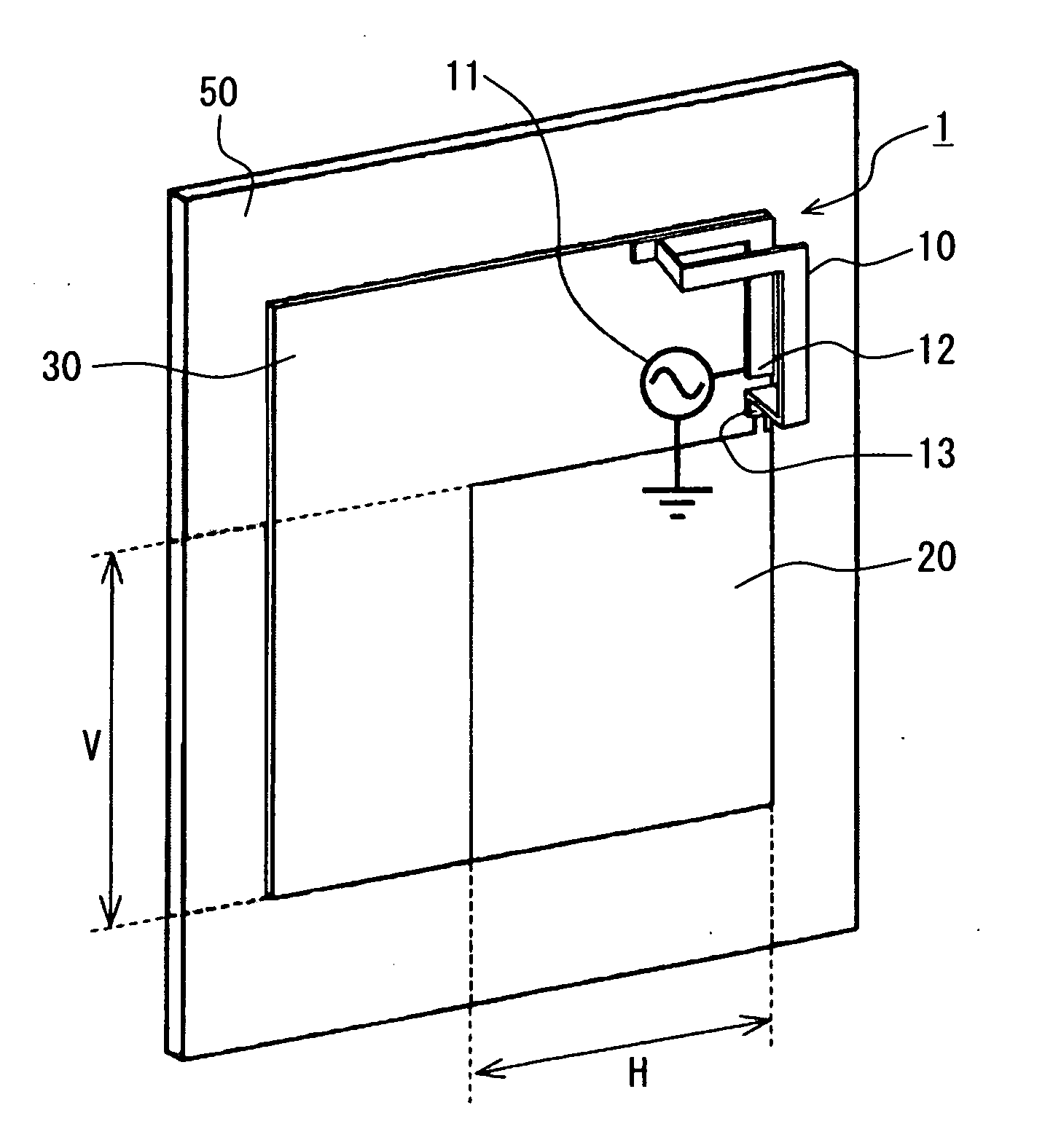
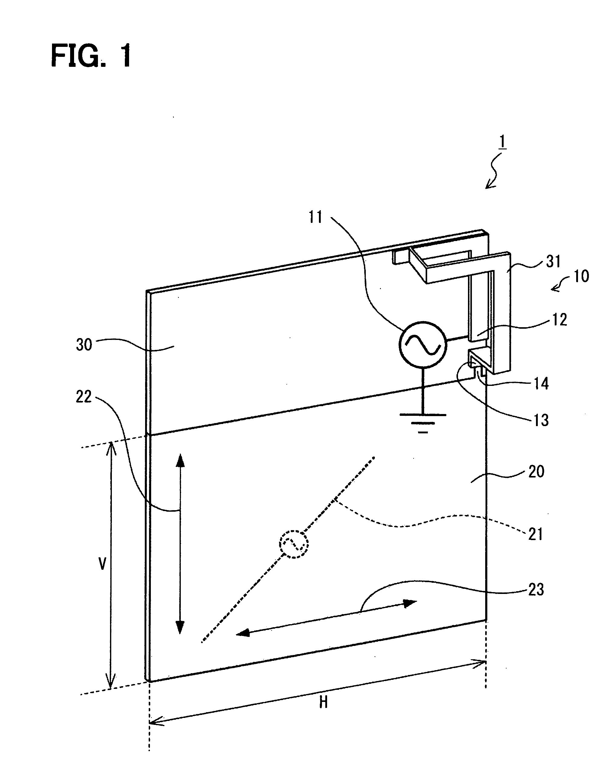
[0022]FIG. 1 shows a whole of an antenna apparatus 1 according to an example embodiment. FIG. 2 shows a small loop antenna 10 in the apparatus 1.

[0023]The antenna apparatus 1 includes a circuit board 30 and a wireless circuit 11, which is disposed on the board 30. Further, the apparatus 1 includes the small loop antenna 10 and a ground substrate 20.

[0024]The circuit board 30 is made of, for example, resin, and a wiring pattern of the wireless circuit 11 is formed on the board 30. Further, various circuit devices are mounted on the board 30. The board 30 is accommodated in a casing (not shown) of a mobile device. The wireless circuit 11 transmits data to and receives data from an external communication device (not shown).

[0025]The small loop antenna 10 in the apparatus 1 includes an antenna element 31 having a loop shape. The antenna element 31 is bent at a middle point of the element 31 by 90 degrees so that the antenna element 31 has a L shape. The small loop antenna 10 has two pol...


PUM


Abstract

An antenna apparatus includes: a ground substrate; and a loop antenna having first and second polarized wave surfaces, which are perpendicular to the substrate. The substrate provides an antenna, which is excited and vibrated together with the loop antenna. The antenna has a first polarized wave component in parallel to the first polarized wave surface and a second polarized wave component in parallel to the second polarized wave surface. A polarized wave ratio between the first polarized wave component and the second polarized wave component in the substrate is substantially equal to a polarized wave ratio between the first polarized wave surface and the second polarized wave surface in the loop antenna.

Description

CROSS REFERENCE TO RELATED APPLICATION[0001]This application is based on Japanese Patent Application No. 2009-86703 filed on Mar. 31, 2009, the disclosure of which is incorporated herein by reference.FIELD OF THE INVENTION[0002]The present invention relates to an antenna apparatus.BACKGROUND OF THE INVENTION[0003]Recently, dimensions of wireless devices and mobile devices such as a mobile terminal are minimized. The mobile terminal is suitably used for a keyless entry system in a vehicle. Thus, it is required to reduce dimensions of an antenna mounted in the mobile terminal.[0004]The above built-in antenna apparatus in the mobile terminal and the like is described in JP-A-2000-244219 (corresponding to EP-1154513). The antenna apparatus is built in a wireless communication terminal for communication, and includes a loop antenna device having a loop surface, which is perpendicular to a substrate.[0005]Since the loop antenna device is perpendicular to the substrate, the loop surface is...

Claims


Application Information

Patent Timeline
IPC IPC(8): H01Q21/00H01Q7/00
CPCH01Q1/3241H01Q7/00H01Q1/48
Inventor KAKUYA, YUUJITAKAOKA, AKIRAWADA, HIDENORIYAMASHITA, KOUJI
Owner DENSO CORP
Learn More