Terminal structure of coil device
a coil device and terminal structure technology, applied in transformers/inductance coils/windings/connections, mechanical equipment, machines/engines, etc., can solve the problems of insufficient calking of conductive wires, unstable joining state, and difficulty in bringing the first and second planar portions in contact evenly, so as to increase the amount of deformation
- Summary
- Abstract
- Description
- Claims
- Application Information
AI Technical Summary
Benefits of technology
Problems solved by technology
Method used
Image

Examples
first embodiment
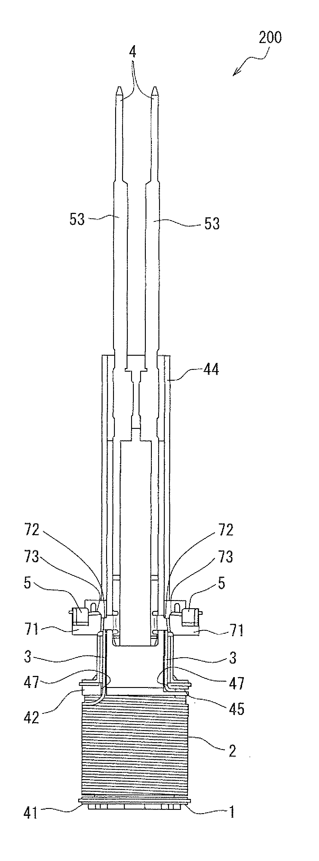
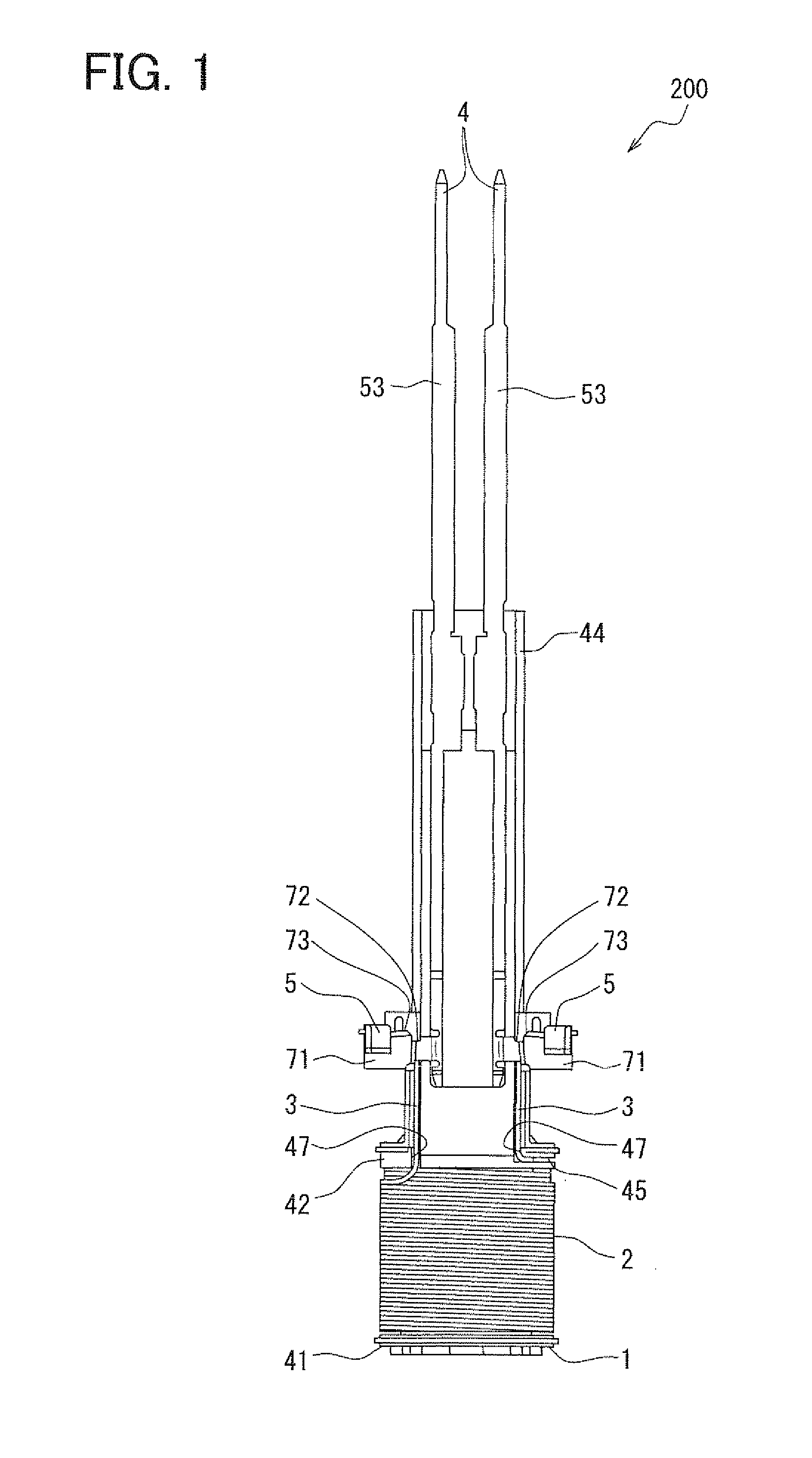
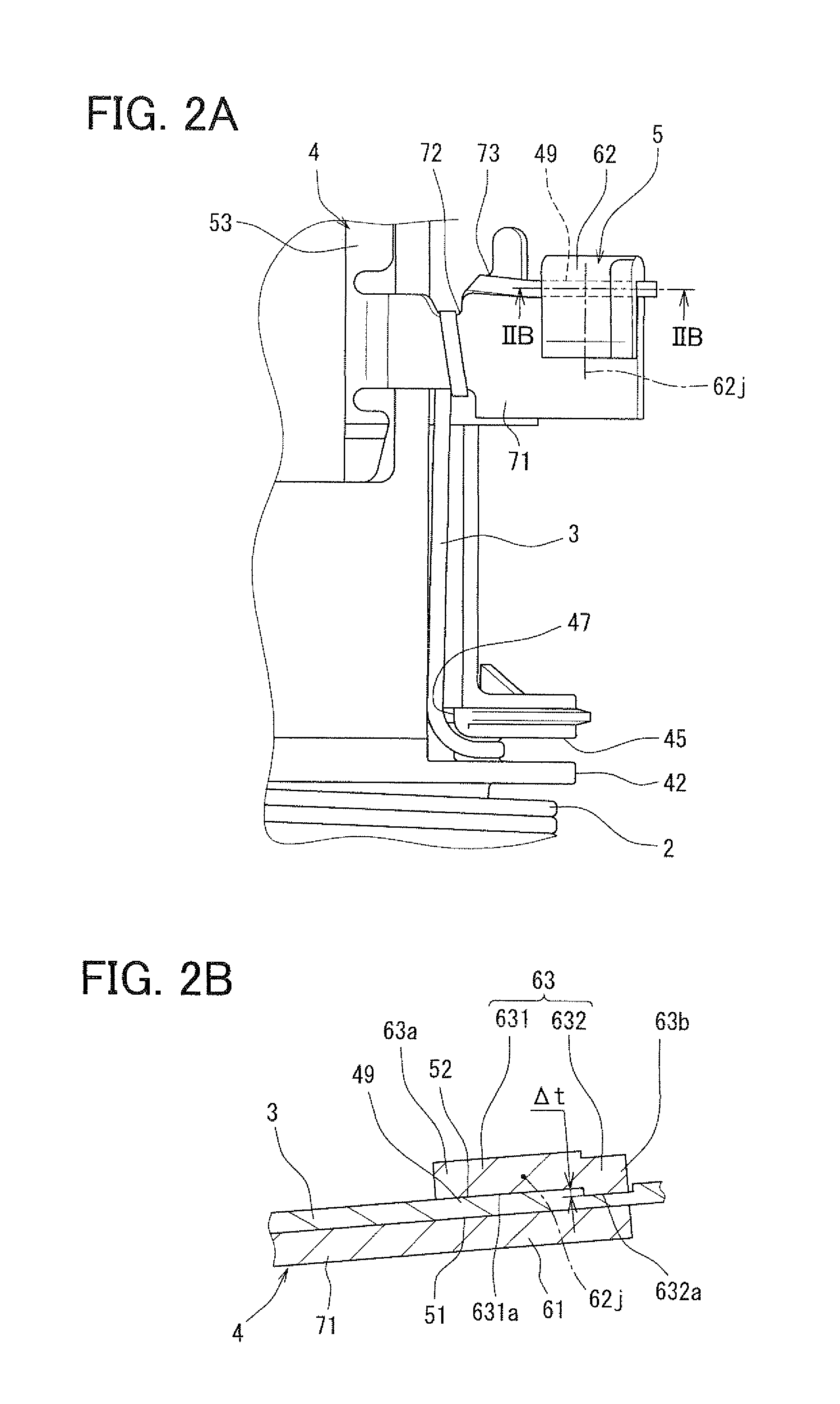
[0024]FIGS. 1 to 4 illustrate a terminal structure of a coil device 200 in accordance with a first embodiment of the invention. FIG. 1 illustrates an example of the coil device 200, and FIGS. 2A to 3C illustrate a characterizing portion of the terminal structure. FIGS. 2A and 2B illustrate a fusing portion, which is a main feature of the terminal structure, and FIGS. 3A to 3C illustrate the terminal structure before temporary calking. FIG. 4 illustrates an example of an injector 100 to which the coil device 200 of the present embodiment is applied.
[0025]The injector 100, to which the coil device 200 of the present embodiment is applied, is used for a direct gasoline-injection engine, for example. The injector 100 may be applied not only to the direct gasoline-injection engine but also to a premixed gasoline engine.
[0026]When the injector 100 is applied to the direct gasoline-injection engine, the injector 100 is disposed on a cylinder head of the engine such that a front end part of...
second embodiment
[0093]A second embodiment of the invention, which is a modification of the first embodiment, is shown in FIG. 5.
[0094]As illustrated in FIG. 5, a stepped portion 632 having a flat surface 632a is formed between an end portion 63a of a contact surface portion 63 on a coil 2-side (lead wire bundle portion 72-side), and an opposite end portion 63b, which is opposite from the coil 2-side end portion 63a. Accordingly, a portion of a lead wire end 49, on which a greater crushing effect by the stepped portion 632 is exerted, is located to be away by a distance L from an adjacent portion of a lead wire end 49, on which the fusing connection is not performed.
[0095]For this reason, conductive wire portions of an intermediate part of the coil lead wire 3 picked out from the coil 2 and the lead wire end 49, which are located on the coil 2-side and on which the fusing connection is not performed, are prevented from being located close to the stepped portion 632. Eventually, the development of ex...
third embodiment
[0099]A third embodiment of the invention, which is a modification of the first embodiment, is shown in FIG. 6.
[0100]As illustrated in FIG. 6, a stepped portion 632 of a contact surface portion 63 includes a bending surface 1632a so that the surface 1632a may be brought into surface contact with a second joint surface 52 of a lead wire end 49. The bending surface 1632a is formed into such a shape that includes an inclined surface 632b which is V-shaped in cross section and that projects toward the second joint surface 52. The bending surface 1632a having the V-shaped inclined surface 632b extends in an orthogonal direction perpendicular to a longitudinal direction of the lead wire end 49, i.e., in the width direction of the lead wire end 49.
[0101]Accordingly, the stepped portion 632 of the present embodiment includes the bending surface 1632a whose sectional shape is the above-described shape projecting toward the second joint surface 52. Thus, a cross section of the stepped portion...
PUM
| Property | Measurement | Unit |
|---|---|---|
| shape | aaaaa | aaaaa |
| structure | aaaaa | aaaaa |
| conductive | aaaaa | aaaaa |
Abstract
Description
Claims
Application Information
 - R&D
- Intellectual Property
- Life Sciences
- Materials
- Tech Scout
- Unparalleled Data Quality
- Higher Quality Content
- 60% Fewer Hallucinations
Browse by: Latest US Patents, China's latest patents, Technical Efficacy Thesaurus, Application Domain, Technology Topic, Popular Technical Reports.
© 2025 PatSnap. All rights reserved.Legal|Privacy policy|Modern Slavery Act Transparency Statement|Sitemap|About US| Contact US: help@patsnap.com