
Bridge sensor with collocated electronics and two-wire interface

Active Publication Date: 2010-09-30
PCB PIEZOTRONICS
View PDF11 Cites 22 Cited by
  • Summary
  • Abstract
  • Description
  • Claims
  • Application Information

AI Technical Summary

Benefits of technology

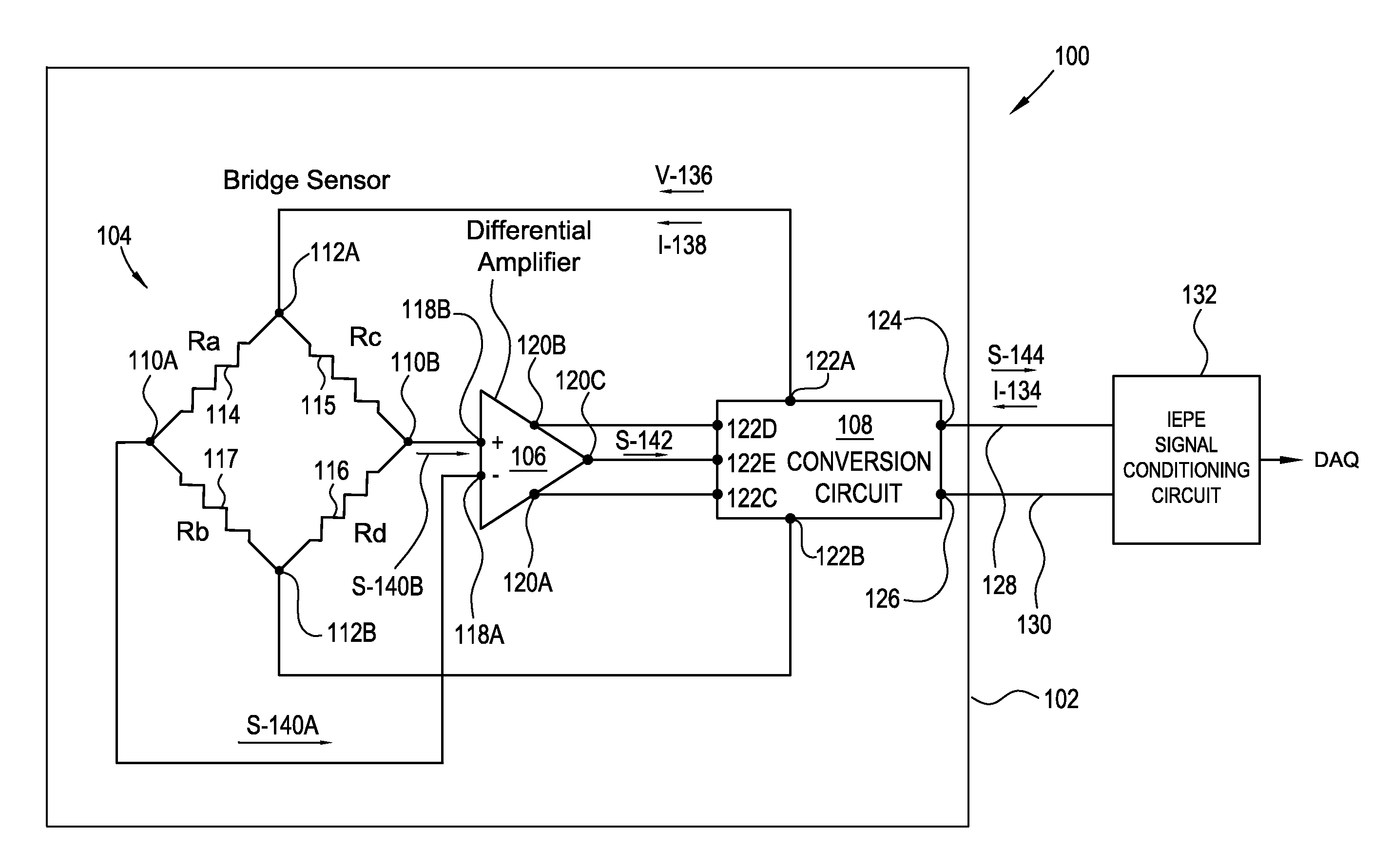
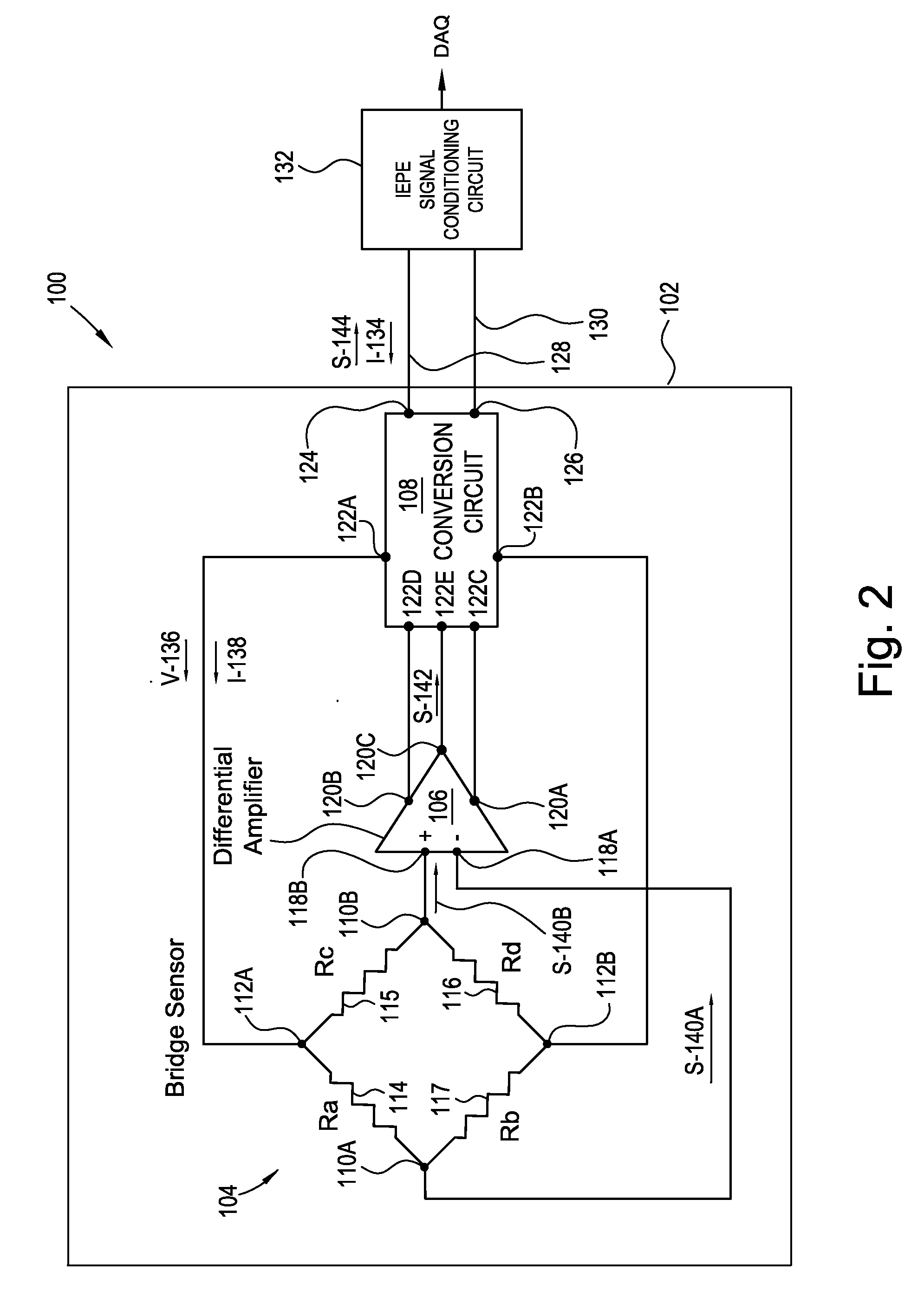
[0029]It is a general object of the present invention to provide a system and means to provide a MEMS sensor with on-board electronics to enable interface with a less well-regulated power source, or a system and means to interface a MEMS sensor with a

Problems solved by technology

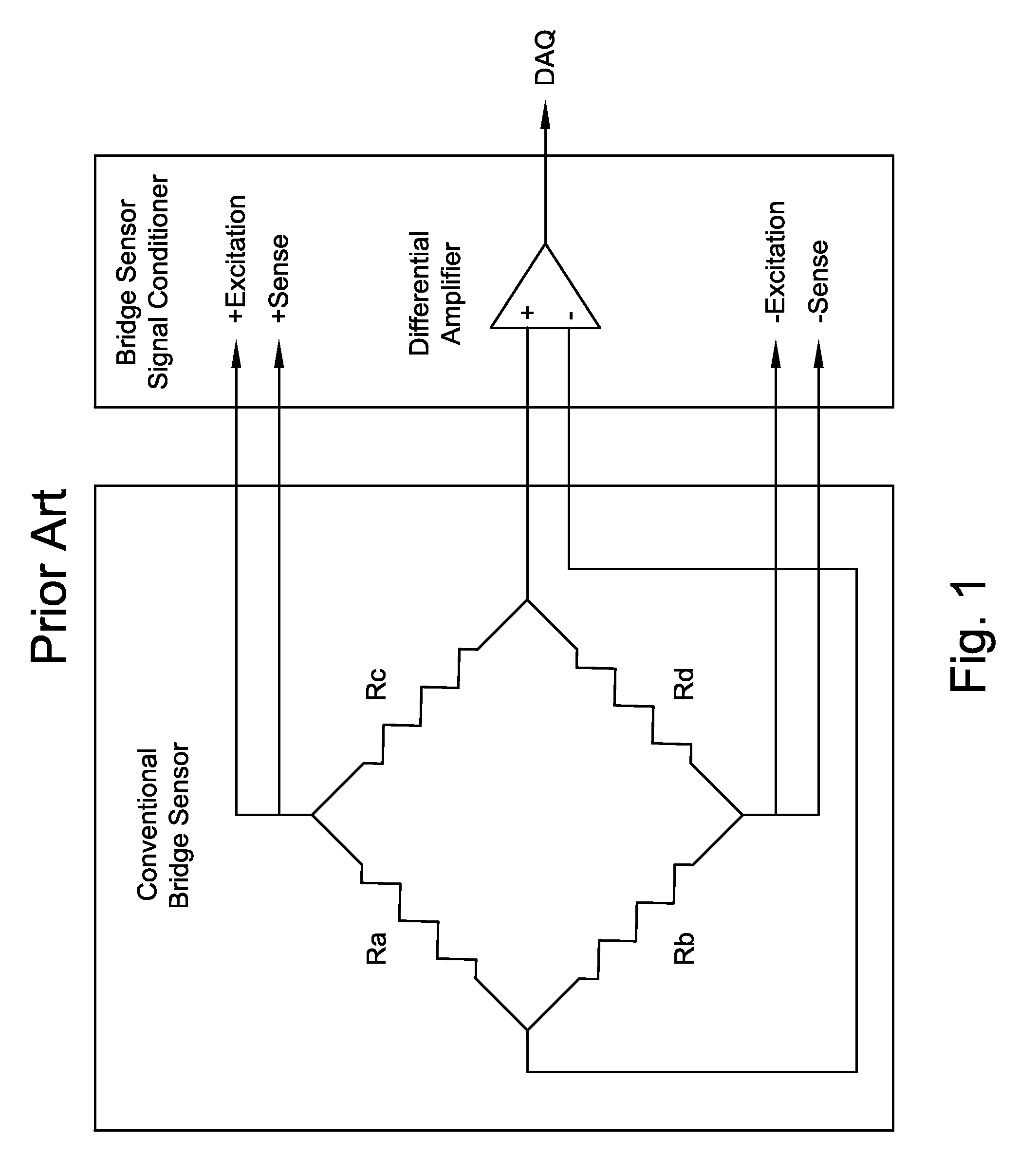
The current for a prior art IEPE circuit is not well regulated, which is adequate for use with a PE bridge sensor.
As a result, a bridge sensor signal conditioner is more complex and costly to manufacture and physically larger than the IEPE circuitry noted supra and more difficult and complicated to operate.

Method used


Image

  • Bridge sensor with collocated electronics and two-wire interface
  • Bridge sensor with collocated electronics and two-wire interface
  • Bridge sensor with collocated electronics and two-wire interface

Examples


Embodiment Construction

[0040]At the outset, it should be appreciated that like drawing numbers on different drawing views identify identical, or functionally similar, structural elements of the invention. While the present invention is described with respect to what is presently considered to be the preferred aspects, it is to be understood that the invention as claimed is not limited to the disclosed aspects.

[0041]Furthermore, it is understood that this invention is not limited to the particular methodology, materials and modifications described and as such may, of course, vary. It is also understood that the terminology used herein is for the purpose of describing particular aspects only, and is not intended to limit the scope of the present invention, which is limited only by the appended claims.

[0042]Unless defined otherwise, all technical and scientific terms used herein have the same meaning as commonly understood to one of ordinary skill in the art to which this invention belongs. Although any meth...


PUM


Abstract

A transducer, including: a housing; a bridge sensor circuit disposed within the housing and including at least one micro electro-mechanical systems (MEMS) sensing elements and first and second output ports; circuitry disposed within the housing; and an input / output (I / O) line electrically connected to the circuitry, accessible at an exterior of the housing, and adapted for receipt of input voltage or current. The circuitry is for generating a single data signal that combines respective outputs of the first and second output ports, and transmitting the DC-coupled single data signal on the I / O line. The circuitry is for generating and transmitting to the bridge sensor circuit an excitation current or voltage using the input voltage or current.

Description

FIELD OF THE INVENTION[0001]The depicted and described embodiments relate to a sensor with Micro Electro Mechanical Systems (MEMS) elements and on-board circuitry for power, thermal sensitivity compensation, and signal conditioning. The depicted and described embodiments also relate to a converter for providing power and signal conditioning for a sensor with MEMS elements.BACKGROUND OF THE INVENTION[0002]Transducers which are used to measure dynamic motion or force exist in extremely large variety, but virtually all consist of two general components: a mechanical structure designed such that the applied motion or force input causes an internal deflection proportional to that input, and an electrical element which measures that deflection in a manner that the electrical output of the sensor is proportional to the magnitude of the deflection. The transduction from deflection to an electrical parameter defines the generic term “transducers” for such devices.[0003]The form of electrical...

Claims


Application Information

Patent Timeline
IPC IPC(8): G01R17/10
CPCG01P15/0802G01R17/10G01P15/123
Inventor HYND, JOHN WILLIAMSILL, ROBERT D.HIGBEE, JAMES R.
Owner PCB PIEZOTRONICS
Learn More