
Armrest with cup holder

Inactive Publication Date: 2010-09-30
TACHI S CO LTD
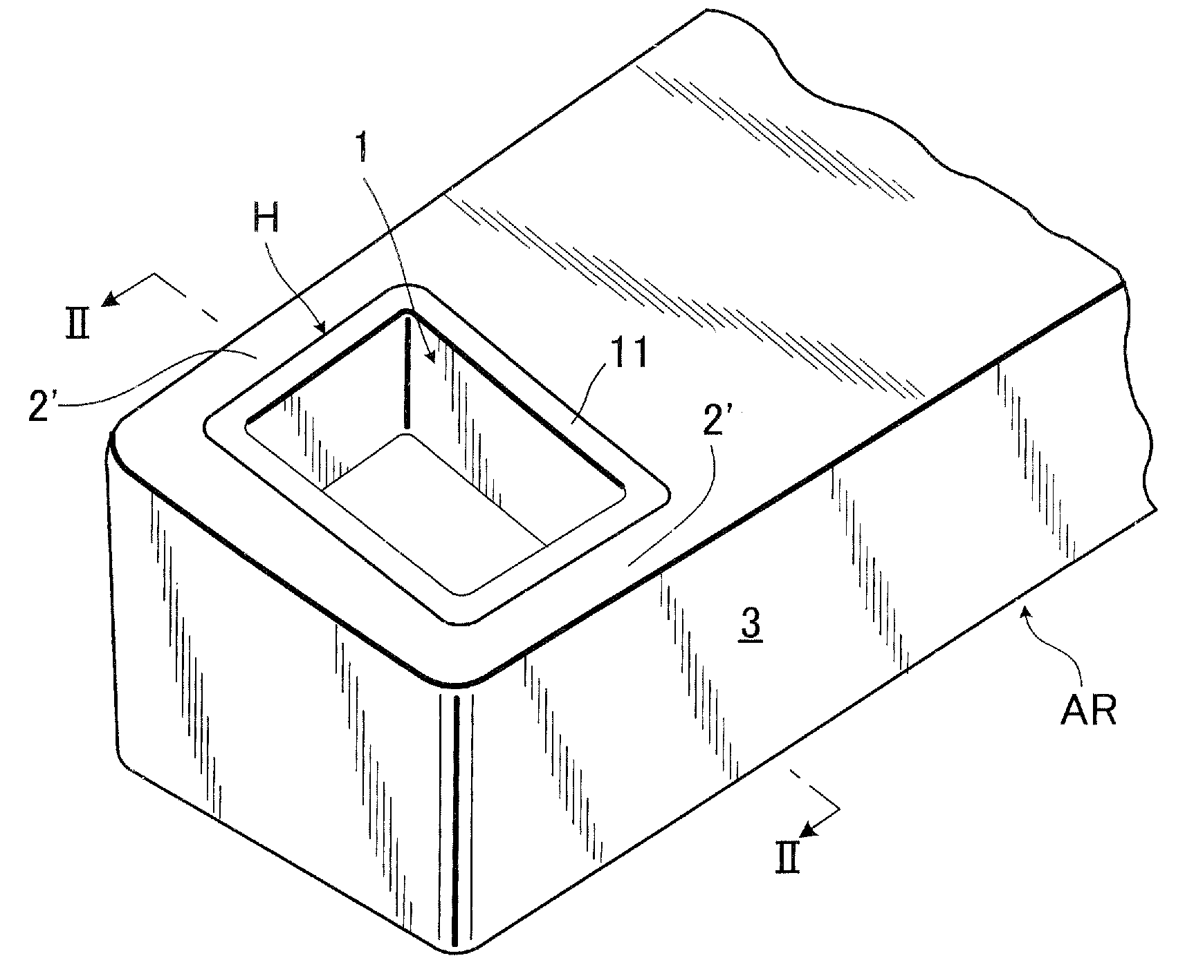
View PDF4 Cites 10 Cited by
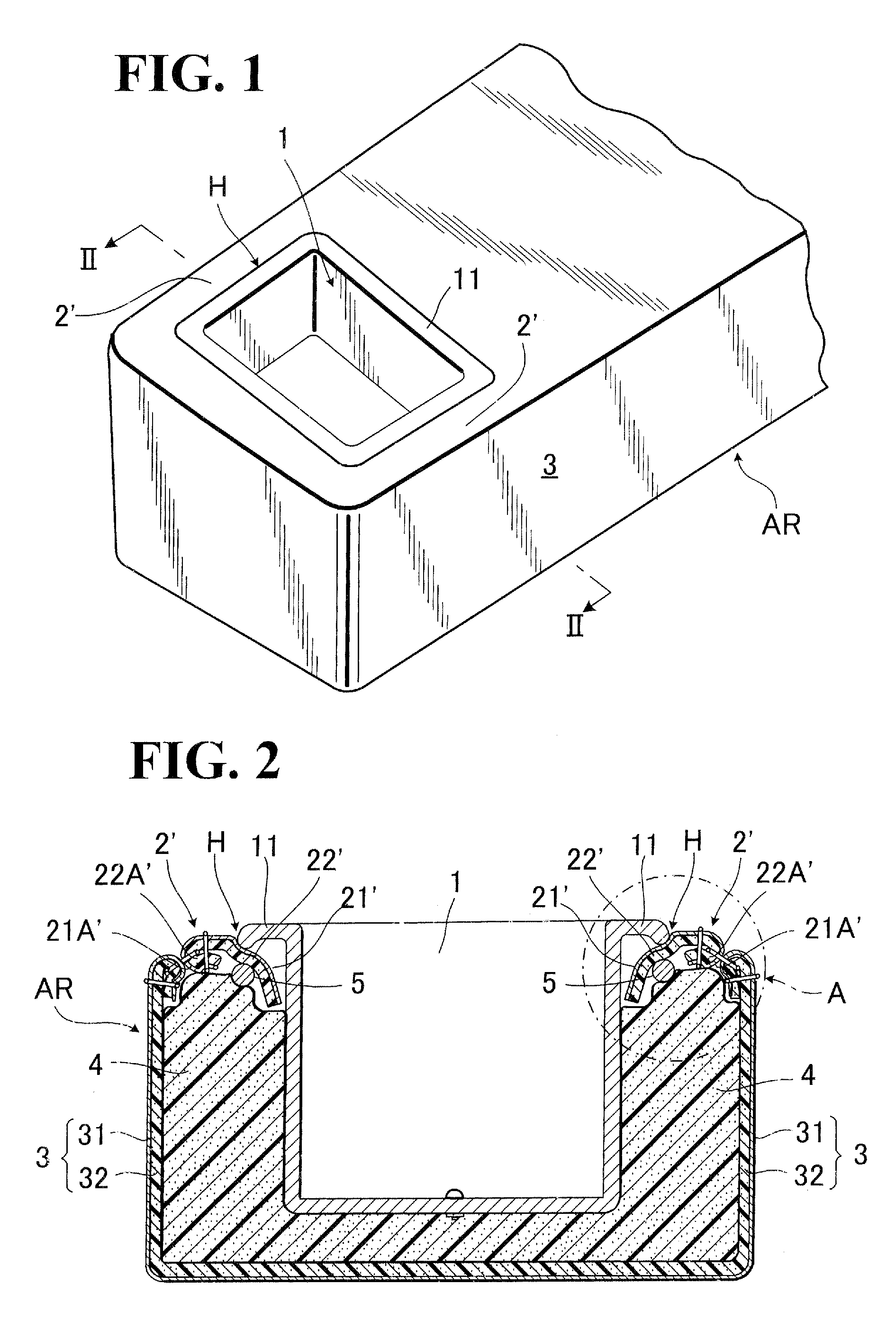
  • Summary
  • Abstract
  • Description
  • Claims
  • Application Information

AI Technical Summary

Benefits of technology

[0014]In view of the above-stated drawbacks, it is a purpose of the present invention to provide an improved armrest with cup holder, which effectively avoids the creation of the aforementioned objectionable recessed areas.

Problems solved by technology

However, the aforementioned conventional armrests have been with the problem that an objectionable recessed area (H) is created between the cup holder flange (11) and the localized connecting portions (2′) of trim cover assembly (1).
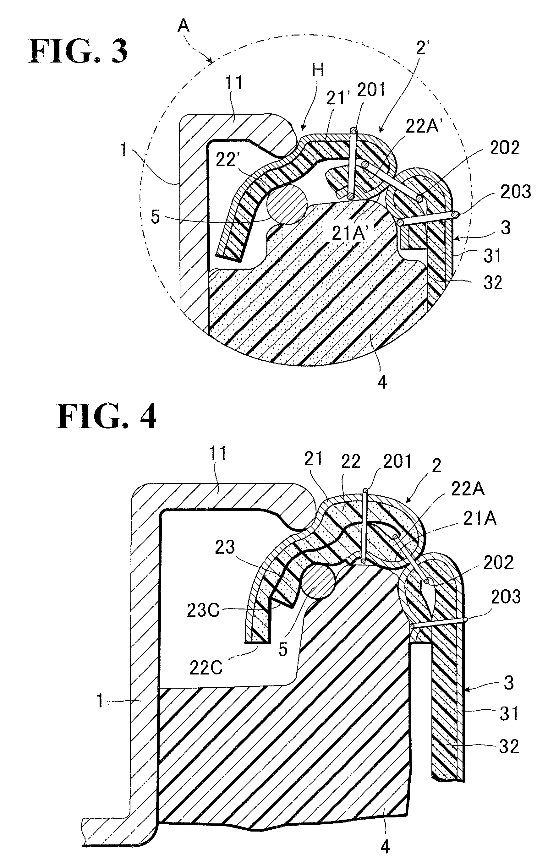
This problem is due to the fact that the free ends of the localized connecting portions (2′) are not sufficiently collapsed by and between the cup holder flange (11) and the support member (5), so that the localized connecting portions (2′) is not made protrudent upwardly around the peripheral end of the flange (11) enough to compensate for and eliminate the recessed area (H).
But, in that case, the flange (11) will be displaced upwardly, which will impair the outer appearance of the armrest.
The reason therefor is that, if the above-described type of armrest is applied to this JP'622 , the support member (5) will contact the support plate of the JP−622 to generate an objectionable or unpleasant noise.

Method used


Image

  • Armrest with cup holder
  • Armrest with cup holder
  • Armrest with cup holder

Examples


Embodiment Construction

[0034]At first, it should be understood that FIGS. 1 to 3 shows a conventional armrest which has been described in the foregoing description of prior art, but, since the present invention is based on such conventional armrest, the armrest (AR) of the present invention uses most of the constituent elements stated in the description of prior art above, the description hereinafter will be made of the armrest (AR) of the present invention, with reference to those FIGS. 1 to 3 as well as to FIGS. 4 and 5.

[0035]Therefore, it should be understood that all like designations given in the conventional armrest described with reference to the FIGS. 1 to 3 correspond to all like designations to be used hereinafter with reference to the FIGS. 4 and 5.

[0036]FIG. 4 shows a principal part of the armrest (AR) in accordance with the present invention. In brief, according to the present invention, a comparative review of FIGS. 3 and 4 indicates that an extension of foam wadding (23) is provided integra...


PUM


Abstract

An armrest with cup holder is disclosed, in which the cup holder is secured in the upper surface thereof, and that upper surface is covered with an upper cover section of trim cover assembly. Localized portions of the afore-said upper cover section, which lie between a flange of the cup holder and a lateral wall of the armrest, are each formed with an extension in the free end thereof. That extension is folded together with the corresponding end of the upper cover section and retained between the flange of cup holder and a support member provided around the flange of cup holder, thereby making protrudent the localized portions to compensate for and eliminate an objectionable recessed areas between those localized portions and cup holder flange.

Description

BACKGROUND OF THE INVENTION[0001]1. Field of the Invention[0002]The present invention relates to an armrest for use with an automotive seat, and in in particular to an armrest of this kind which is provided with a cup holder for receiving and holding a cup or container therein.[0003]2. Description of Prior Art[0004]As shown in FIG. 1 to 3 for example, there has been known an armrest (AR) provided with a cup holder (H) in the upper surface thereof. The cup holder includes a flange (11).[0005]FIGS. 2 and 3 show a cross-sectional view illustrative of structure of the armrest (AR). It is seen therefrom that a foam padding (4) is provided therein, which has a bore receiving a cup holder (1) having a flange (11), wherein the opened side of the cup holder (1) as well as the flange (11) are situated on the upper surface side (at 2′) of the armrest, and that the trim cover assembly (1) covers a substantive whole outer surfaces of the foam padding (4), except that an opening is defined in the...

Claims


Application Information

Patent Timeline
IPC IPC(8): A47C7/62B60N2/75
CPCB60N2/468B60N3/101B60N2/58B60N2/5816B60N2/79
Inventor MIYAZAKI, SEIICHIROSUZUKI, TAKAHIKO
Owner TACHI S CO LTD
Learn More