
Surgical tray methods and apparatus

a surgical console and tray technology, applied in the direction of surgical instrument support, supporting apparatus, application, etc., can solve the problems of difficult storage and transportation of such surgical consoles, unsatisfactory known surgical consoles in a number of respects, and restrict the movement of the tray and arms

Active Publication Date: 2010-09-30
JOHNSON & JOHNSON SURGICAL VISION INC
View PDF15 Cites 3 Cited by
  • Summary
  • Abstract
  • Description
  • Claims
  • Application Information

AI Technical Summary

Benefits of technology

The present invention is related to a tray assembly with an articulatable arm assembly. The arm assembly can hold a tray and can be locked in place using a locking mechanism. The tray can be rotated between a horizontal position and a stored position. The arm assembly includes a frictional hinge with adjustable contact force between a tapered pin and a tapered bushing. The technical effects of this invention include improved stability and flexibility of the tray assembly, as well as improved locking mechanisms for securely holding the tray in place.

Problems solved by technology

Known surgical consoles are unsatisfactory in a number of respects.
Such release cables often restrict the movement of the tray and arms, as they cannot generally accommodate a wide range of tray positions, and thus can easily become tangled in the arms and related interconnects.
Furthermore, as conventional tray systems maintain the tray in a generally horizontal position, the storage and transport of such surgical consoles can be difficult, as the tray extends a significant distance outward from the console in an unlocked position.
This results in a non-compact and difficult-to-transport configuration.
Moreover, the various hinges and interconnects used in conventional surgical console arm assemblies tend to allow the tray to swing outward with very little resistance, and are often ineffective in keeping the tray in a specific desired location and orientation.
In addition, such conventional hinges are subject to hysteresis.

Method used


Image

  • Surgical tray methods and apparatus
  • Surgical tray methods and apparatus
  • Surgical tray methods and apparatus

Examples


Embodiment Construction

[0018]The following detailed description is merely illustrative in nature and is not intended to limit the invention or the application and uses of the invention. Furthermore, there is no intention to be bound by any expressed or implied theory presented in the preceding technical field, background, brief summary or the following detailed description. The invention may be described herein in terms of functional and / or logical block components and various processing steps. For the purposes of conciseness, conventional techniques and systems related to surgical tray systems, hydraulics, friction hinges and the like are not and need not be described in detail herein.

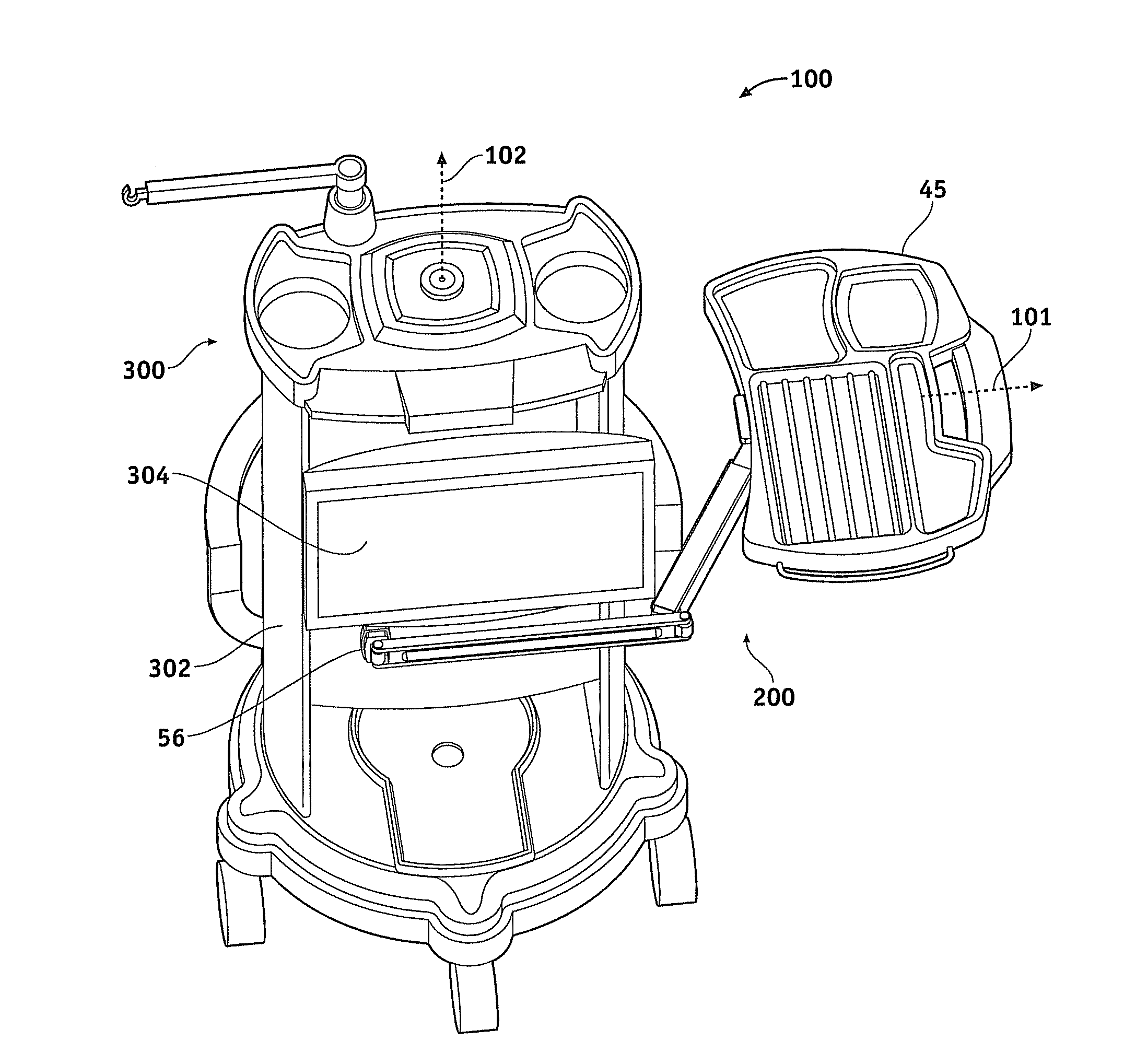
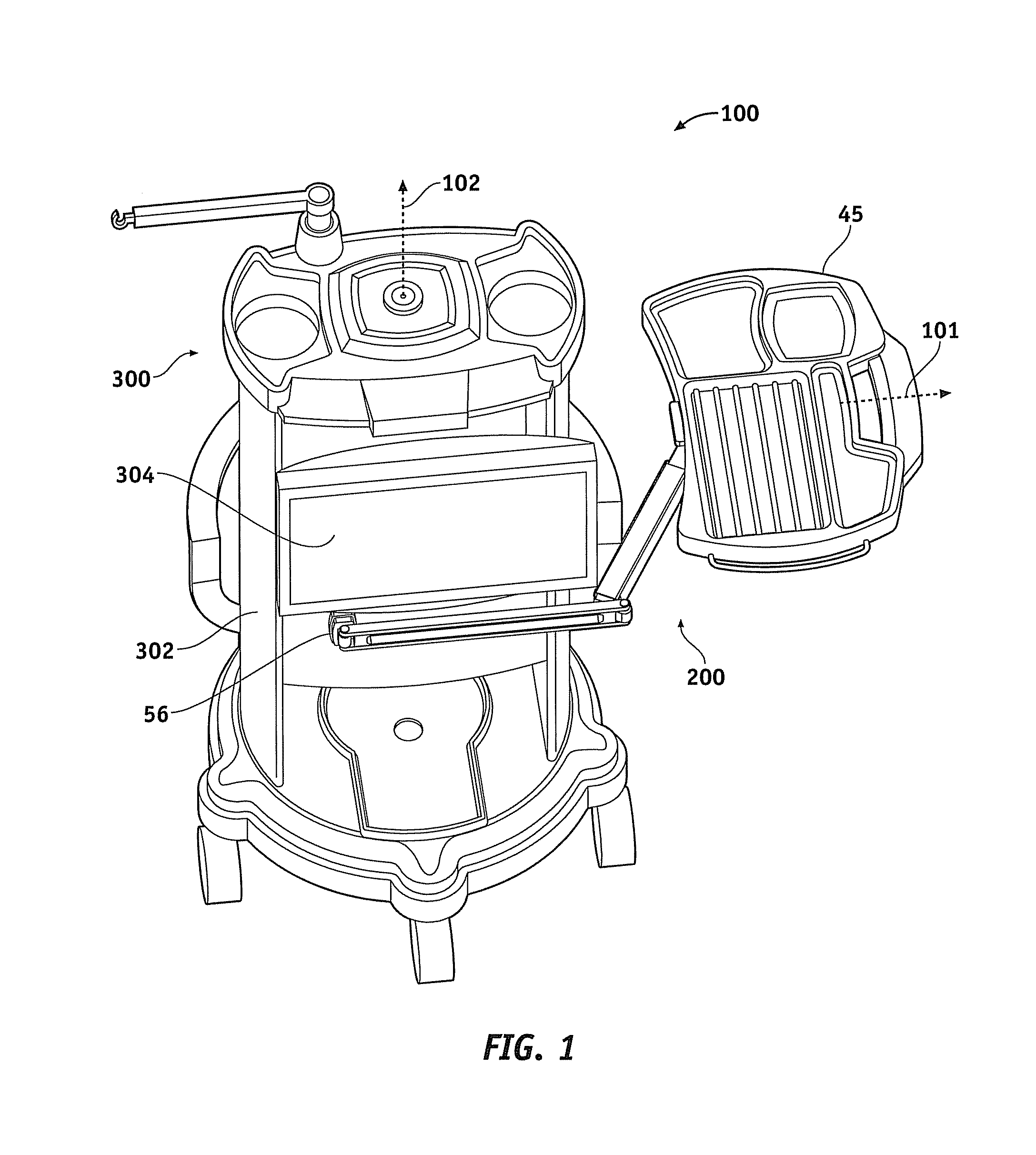
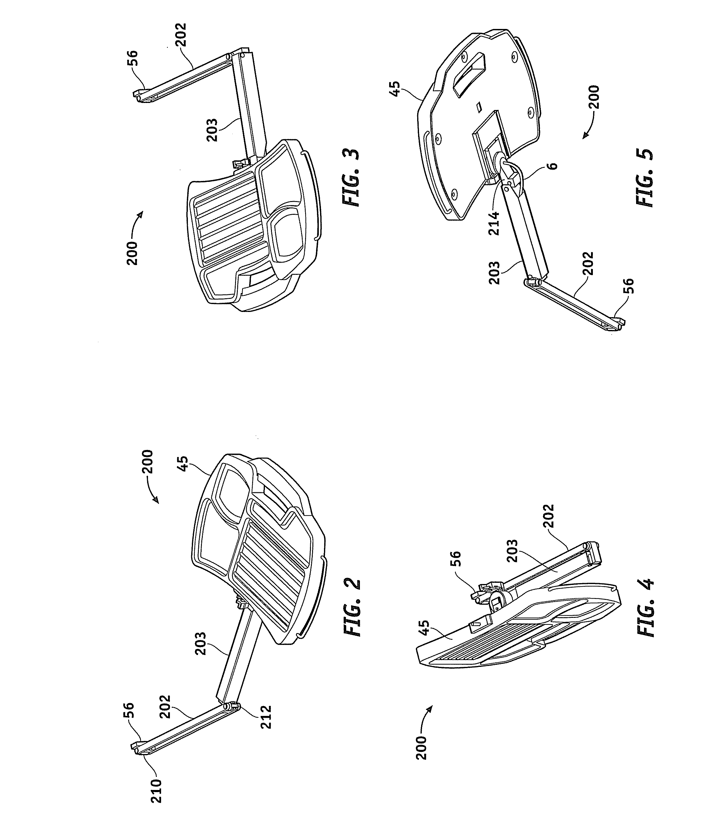
[0019]Referring now to FIG. 1, a surgical console system 100 in accordance with one embodiment of the present invention generally includes a surgical console 300 having a tray 45 coupled with a console body (or simply “body”) 302 via a tray arm 200 having any number of articulating interconnects and linkages as described in...


PUM


Abstract

A tray assembly includes an articulatable arm assembly coupled with a tray and selectively held in place by a locking mechanism (e.g., a locking gas spring). A release mechanism coupled with the tray selectively activates and deactivates the gas shock mechanism and is coaxial with and free rotating with respect to an axis of rotation of the tray. The tray may rotate between a horizontal position and a stored position substantially orthogonal to the horizontal position. The arm assembly may include at least one frictional hinge comprising a tapered pin, a tapered bushing in rotational frictional contact with the tapered pin, and an adjustment mechanism coupled to the tapered pin to provide adjustable contact force between the tapered pin and the tapered bushing.

Description

TECHNICAL FIELD[0001]The present invention generally relates to surgical tray systems, and more particularly relates to articulatable surgical tray assemblies of the type used in connection with portable surgical consoles.BACKGROUND[0002]Surgical consoles generally include, among other things, a tray configured to articulate with respect to a console. One or more interconnected arms coupled to the tray are selectively secured in place via a locking mechanism, such as a gas spring or the like. During use, the tray is configured to remain horizontal, and the operator manually engages or disengages the locking mechanism to reposition the arms and tray in the desired position.[0003]Known surgical consoles are unsatisfactory in a number of respects. For example, the use of gas springs typically requires incorporating some form of release mechanism, such as a release cable, between the tray and the gas spring. Such release cables often restrict the movement of the tray and arms, as they c...

Claims


Application Information

Patent Timeline
Patent Type & Authority Applications(United States)
IPC IPC(8): A47F3/14F16M13/00
CPCA61B19/0248A61B19/0256A61B19/0271A61M2209/082A61B2017/00199A61B2019/025A61B19/26A61B90/50A61B50/10A61B50/13A61B50/20A61B50/33
Inventor ROSS, MARK W.
Owner JOHNSON & JOHNSON SURGICAL VISION INC
Learn More