
Tubular soil auger and manufacturing method

a technology of tubular soil and manufacturing method, which is applied in the field of earth-moving equipment, can solve the problems of inability to form clean holes, damage to the tool, the machine or the operator, and the inherently limited utility of solid tools with a large volume, and achieve the effect of less wobbling or shaking and high speed

Active Publication Date: 2010-09-30
PAXTON FR
View PDF7 Cites 15 Cited by
  • Summary
  • Abstract
  • Description
  • Claims
  • Application Information

AI Technical Summary

Benefits of technology

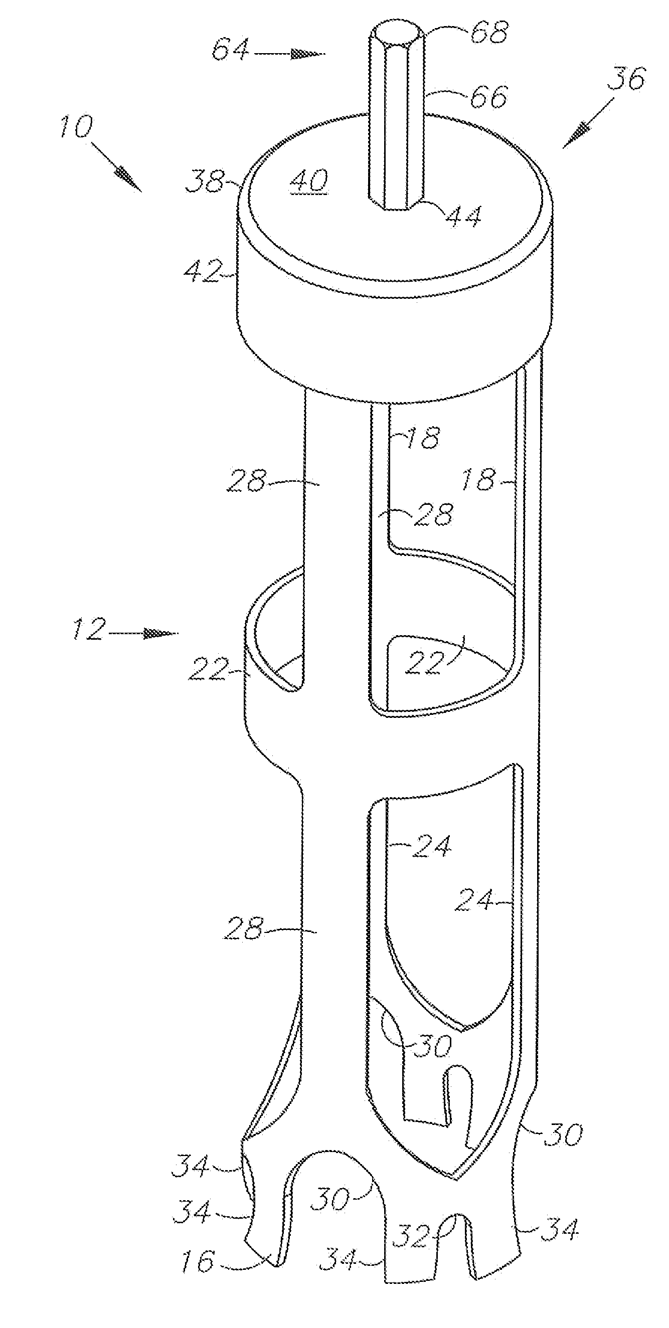
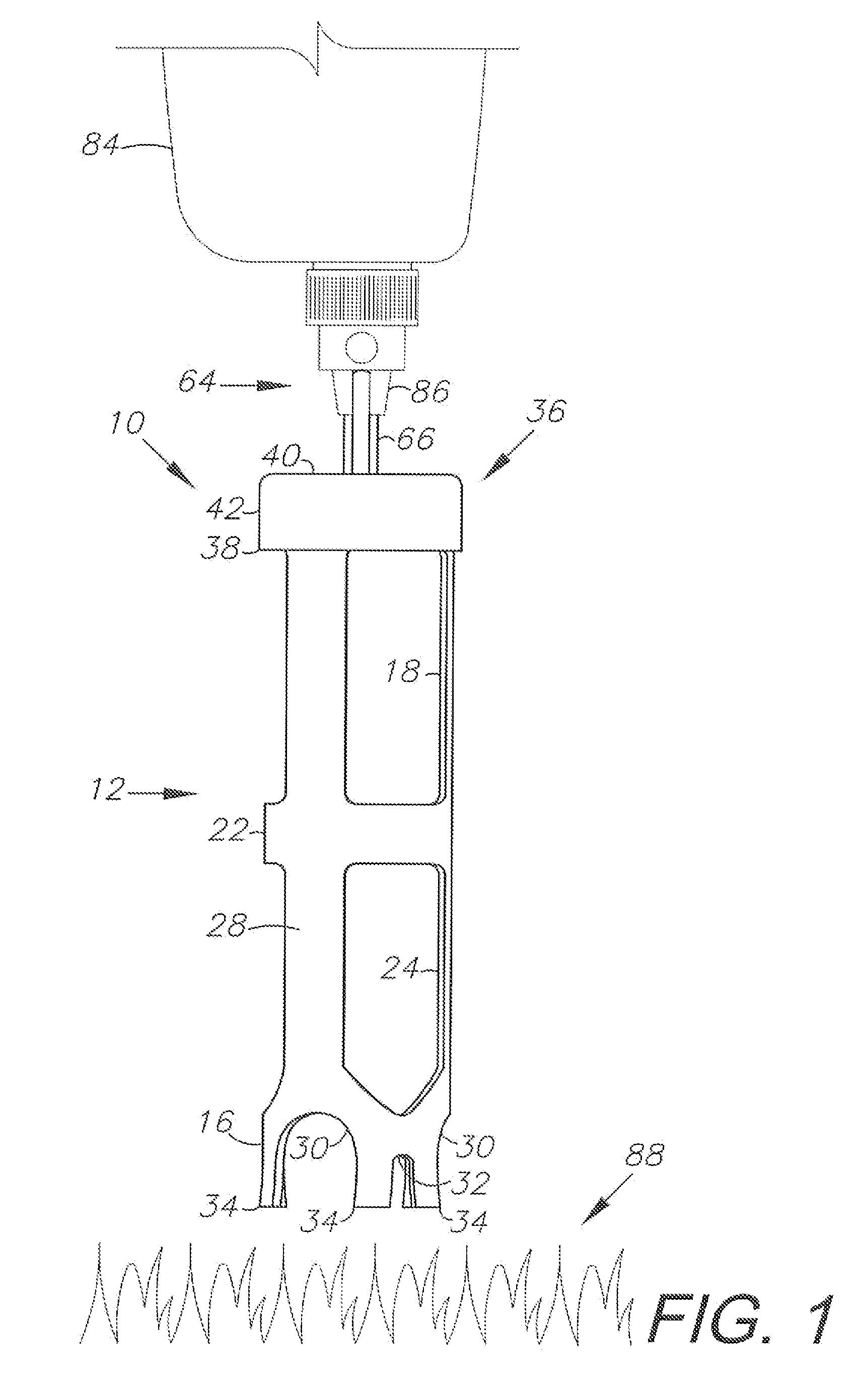
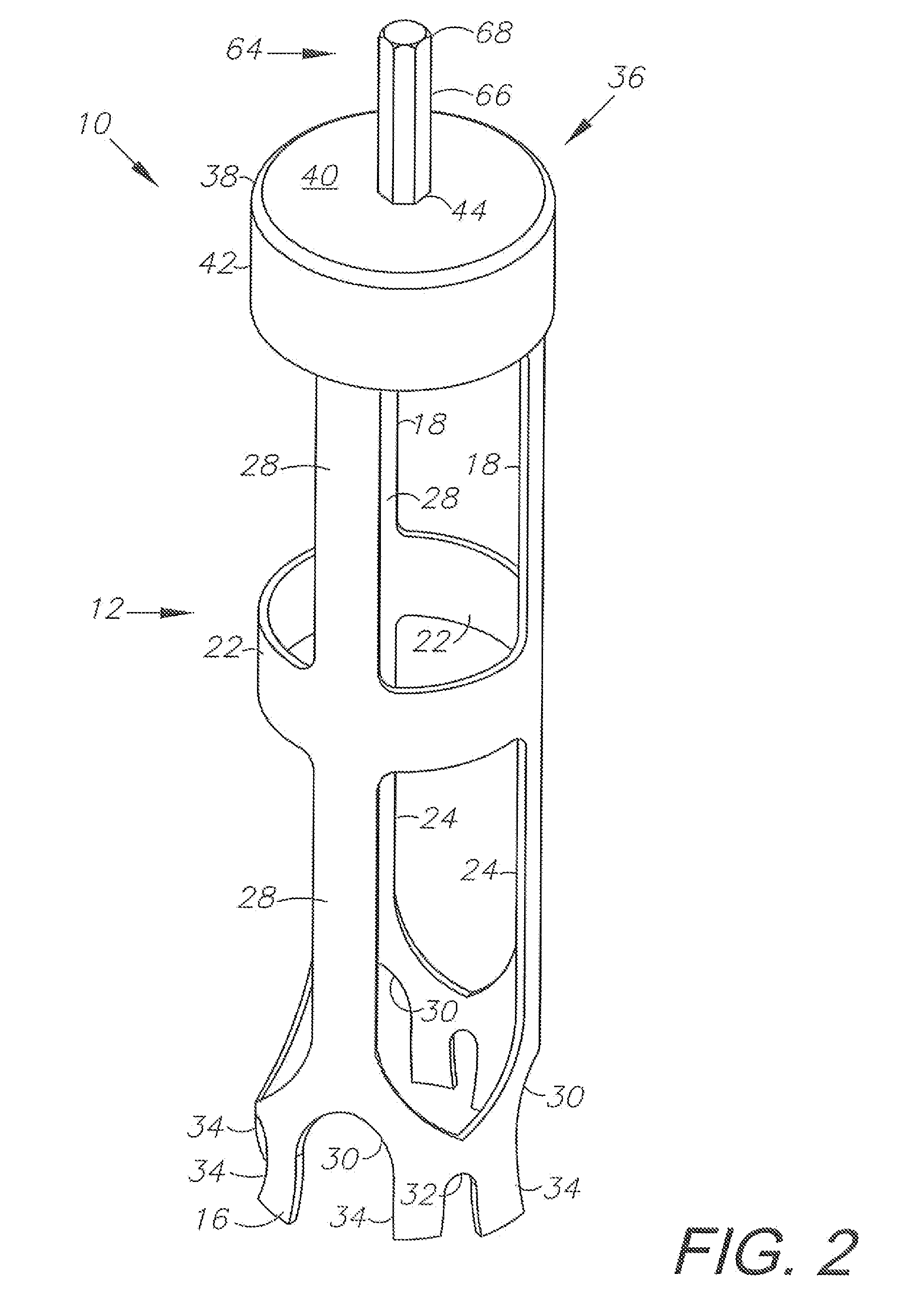
[0010]An auger having a tubular body with a central axis is adapted for use with a rotational power source for creating smooth-walled cylindrical holes in the earth. The auger is manufactured using precision cutting tools to create apertures and notches in the tubular body without deforming the concentricity of the tubular body. A cap assembly is attached to an end of the tubular body and includes a pair of opposing, upwardly-open tubes; an inner cap, and an outer cap. Each cap has a unique centrally-located aperture located in an end wall wherein the aperture is aligned with the central axis of the tubular body. The alignment of the cap apertures, the unique configuration of the cap apertures, and the distance between the cap apertures ensures proper alignment and secure engagement of a shaft that is attached to a rotational power source, such as an electric drill. Identifying a preferred distance between cap apertures for a given tubular body length, and manufacturing a tubular body using precision cutting tools and precision welding, produces a tool that may be rotated at high speed with less wobbling or shaking about the central vertical axis of the tool.

Problems solved by technology

However, solid tools with a large volume are inherently limited in their utility and the types of machines that can effectively provide enough torque to rotate the tool and create a hole.
However, with tubular tools, if the mass of the tool is not equally balanced, distributed, and aligned along the central vertical axis of the tool, rotation of tool at high speed makes the tool susceptible to wobbling or shaking resulting in damage to the tool, machine, or operator, or difficulty forming a clean hole.
However, conventional methods of manufacture employ die presses to remove material that can distort the roundness of the tubular wall thereby affecting the balance and distribution of mass of the tool.
As a result, such tools are susceptible to wobbling and shaking during use, and have difficulty forming clean holes.

Method used


Image

  • Tubular soil auger and manufacturing method
  • Tubular soil auger and manufacturing method
  • Tubular soil auger and manufacturing method

Examples


Embodiment Construction

I. Introduction and Environment

[0021]As required, detailed aspects of the present invention are disclosed herein; however, it is to be understood that the disclosed aspects are merely exemplary of the invention, which may be embodied in various forms. Therefore, specific structural and functional details disclosed herein are not to be interpreted as limiting, but merely as a basis for the claims and as a representative basis for teaching one skilled in the art how to variously employ the present invention in virtually any appropriately detailed structure.

[0022]Certain terminology will be used in the following description for convenience in reference only and will not be limiting. For example, top, upper, bottom, and lower refer to the invention as orientated in the view being referred to. Said terminology will include the words specifically mentioned, derivatives thereof and words of similar meaning.

II. Preferred Embodiment Tubular Auger 10

[0023]Referring to the drawings in more det...


PUM

PropertyMeasurementUnit
heightaaaaaaaaaa
rotational poweraaaaaaaaaa
lengthaaaaaaaaaa

Abstract

A soil auger for creating smooth-walled cylindrical holes in the earth is provided for use with a drill. The auger has a central rotational axis with a tubular body that is open at a bottom cutting end, and enclosed at a top end by a cap assembly. The cap assembly has a top wall and a bottom wall. The top and bottom walls have apertures aligned with the central rotational axis for receiving a shaft in alignment therewith, and for attachment to a drill. The distance between the top wall and bottom wall compared to the overall length of the assembled auger determines the minimum height of the cap assembly to minimize the rotational imbalance of the auger during use for a given body length. A method of manufacturing the auger is provided using precision cutting tools to create apertures in the body and to maintain concentricity of the auger components.

Description

CROSS-REFERENCE TO RELATED APPLICATIONS[0001]This application claims priority in Provisional Patent Application No. 61 / 165,260, filed Mar. 31, 2009, which is incorporated herein by reference.BACKGROUND OF THE INVENTION[0002]1. Field of the Invention[0003]The present invention relates generally to earth working equipment, and in particular a tubular soil auger for creating a cylindrical hole in the ground.[0004]2. Description of the Related Art[0005]A cylindrical cutting tool that rotates along a central vertical axis enables a user to create a cylindrical hole. A solid cylindrical tool, such as a drill bit, removes a volume of material displaced by the volume of the tool. The larger the cross-section of the solid tool, the larger the diameter of hole that may be created. However, solid tools with a large volume are inherently limited in their utility and the types of machines that can effectively provide enough torque to rotate the tool and create a hole. A hollow, rotating tubular ...

Claims


Application Information

Patent Timeline
Patent Type & Authority Applications(United States)
IPC IPC(8): E21B10/02B23P15/28B23K26/38B26F3/00
CPCB23K26/38Y10T29/49995E21B10/02B26F3/004Y10T83/0591
Inventor PAXTON, III, FRANK
Owner PAXTON FR
Learn More