Power supplying system for a sliding structure

a technology of sliding structure and power supply system, which is applied in the direction of insulated conductors, cables, conductors, etc., can solve the problem of reducing the harness-slack-absorbing performan

Active Publication Date: 2010-09-30
YAZAKI CORP +1
View PDF6 Cites 15 Cited by
  • Summary
  • Abstract
  • Description
  • Claims
  • Application Information

AI Technical Summary

Benefits of technology

[0015]These and other objects, features, and advantages of the present invention will become m...

Problems solved by technology

In particular, if the protector cover 42b is absent, the wiring harness 46 may interfere with other parts at an outside to generate noise, or may malfunction to ...

Method used


Image

  • Power supplying system for a sliding structure
  • Power supplying system for a sliding structure
  • Power supplying system for a sliding structure

Examples


Embodiment Construction

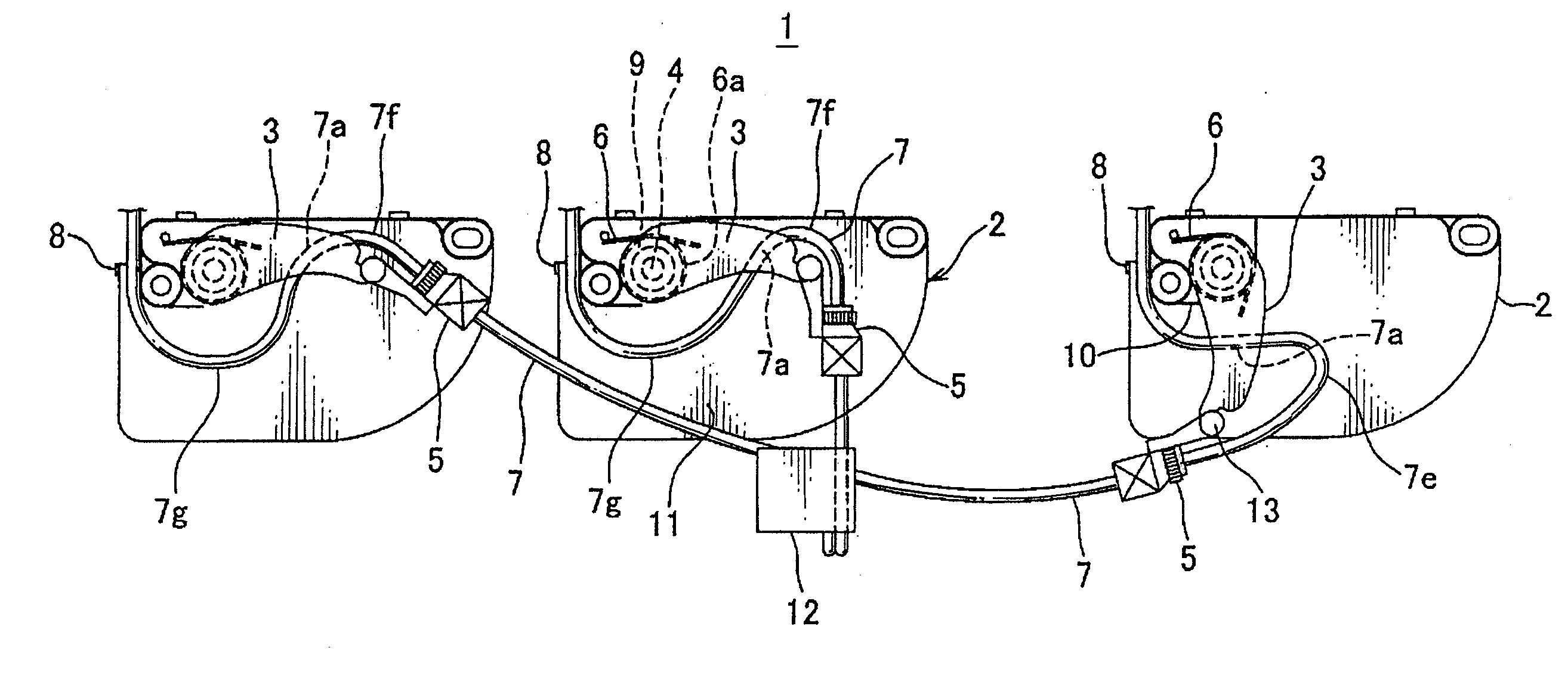
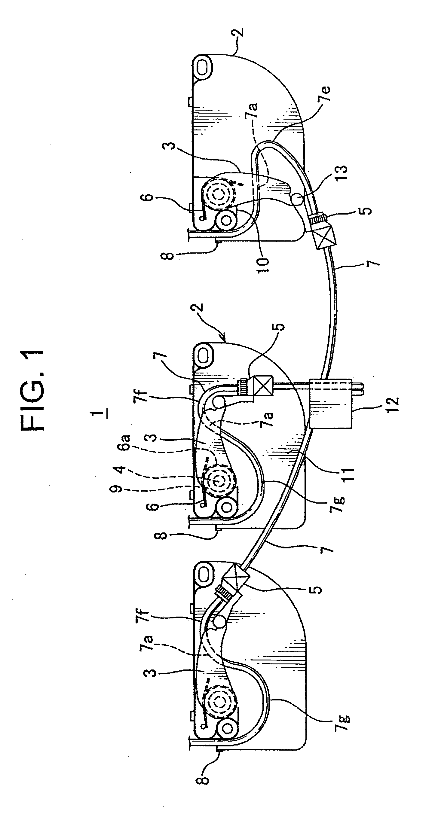
[0025]FIG. 1 is a front view showing a first embodiment of power-supplying system for a sliding structure according to the present invention.

[0026]In FIG. 1, a right side view shows a power-supplying system of a right-side sliding door (not shown) of a vehicle as a sliding structure in a full-open state, a center view shows the power-supplying system of the sliding door in a half-open state, and a left side view shows the power-supplying system of the sliding door in a fully-closed state. Incidentally, as shown in FIG. 7, when the power-supplying system is mounted on a left-side sliding door, the operating modes are inverted from FIG. 1.

[0027]A first feature of this power-supplying system 1 is that a synthetic resin-made or metallic link arm 3 is rotatably mounted on a synthetic resin-made protector base 2 with a rotating shaft 4, a harness holding member 5 is rotatably mounted on a tip end of the link arm 3, a metallic torsion coil spring 6 urges the link arm 3 upward in a counter-...


PUM


Abstract

A link arm is rotatably supported by a rotating shaft along a protector base, and urged in a harness-slack-absorbing direction by a torsion coil spring. A wiring harness is fixed to a harness-holding member at a tip end of the link arm and to a harness-fixing portion of the protector base, and routed flexibly between the harness-holding member and the harness-fixing portion via between the protector base and an opposite wall of the link arm opposite to the protector base.

Description

CROSS REFERENCE TO RELATED APPLICATIONS[0001]This application is on the basis of Japanese Patent Application No. 2009-081196, the contents of which are hereby incorporated by reference.BACKGROUND OF THE INVENTION[0002]1. Field of the Invention[0003]The present invention relates to a power-supplying system for a sliding structure in which a wiring harness is routed along a link arm for continuously supplying electric power to such as a sliding door of a vehicle.[0004]2. Description of the Related Art[0005]FIG. 7 shows an embodiment of a conventional power-supplying system for a sliding structure (See Patent Document 1).[0006]In this power-supplying system 41, a link arm 43 is pivotally supported in a synthetic resin made protector 42 at a sliding door side of a vehicle, and a metallic torsion coil spring 44 is attached to a shaft 50 of the link arm 43. The link arm 43 is urged upward by the coil spring 44. A harness holder 45 is provided at a tip end of the link arm 44. The wiring ha...

Claims


Application Information

Patent Timeline
IPC IPC(8): H02G3/04
CPCH02G11/003B60R16/027
Inventor KATOU, MITSUNOBUYAMASHITA, HIROSHINISHIMURA, TOMOAKIINAGAKI, MOTONARI
Owner YAZAKI CORP
Why Eureka
Try Eureka