Adsorption control method and controller

a technology of adsorption control and controller, applied in the direction of hydrogen separation using solid contact, separation process, products, etc., can solve the problem that the feed cycle time cannot be continuously adjusted

Active Publication Date: 2010-09-30
PRAXAIR TECH INC
View PDF24 Cites 14 Cited by
  • Summary
  • Abstract
  • Description
  • Claims
  • Application Information

AI Technical Summary

Benefits of technology

[0017]In another aspect of the present invention, a control system for an adsorbent bed unit is provided. In such control system, a sampling portal is located within an adsorbent bed of the adsorbent bed unit for sampling an adsorbent bed concentration of an impurity within the adsorbent bed. The adsorbent bed adsorbs the impurity from a feed stream fed into the adsorbent bed during a feed cycle time, thereby to produce a product stream containing a product concentration of the impurity no greater than a targeted product concentration. A gas analyzer is operatively associated with the sampling portal and configured to generate data referable to the adsorbent bed concentration. A product purity controller, responsive to the data, is configured to calculate a control parameter that will set a feed cycle time employed within the adsorbent bed unit so that the adsorbent bed concentration will be controlled by the control parameter to approach a targeted adsorbent bed concentration that will maintain the product concentration of the impurity at the level no greater than the targeted product concentration. The control parameter is calculated so that the feed cycle time decreases as the adsorbent bed concentration increases and increases as the adsorbent bed concentration decreases. The sampling portal is situated at a location of the adsorbent bed at which the adsorbent bed concentration will change before the product concentration of the impurity within the product stream changes in response to a disturbance so that controlling the adsorbent bed concentration to approach the targeted adsorbent bed concentration will also maintain the product concentration of the impurity within the product stream at level no greater than the targeted product concentration.
[0021]In another specific embodiment of the present invention, the impurity is a first impurity, the adsorbent bed concentration is a first adsorbent bed concentration, the product concentration is a first product concentration and the targeted product concentration is a first targeted product concentration. The adsorbent bed is configured to adsorb the first impurity and also a second impurity in a first layer of the adsorbent bed and a third impurity in a second layer of the absorbent bed located adjacent to and upstream of the first layer. As such, the adsorbent bed concentration is a first adsorbent bed concentration of the first impurity within the first layer so that the first adsorbent bed concentration will tend to approach a first targeted adsorbent bed concentration, the product stream is produced also having a second product concentration of the second impurity no greater than a second targeted product concentration and a second adsorbent bed concentration of the third impurity within the second layer will be no greater than a second targeted adsorption bed concentration selected so as to prevent break through of the third impurity to the first layer.

Problems solved by technology

The problem with such control would be that the feed cycle time cannot be continually adjusted and the unit would have to be programmed to discard an outlying result based upon a transient condition either in the feed or in the operation of the analyzers themselves.

Method used


Image

  • Adsorption control method and controller
  • Adsorption control method and controller
  • Adsorption control method and controller

Examples


Embodiment Construction

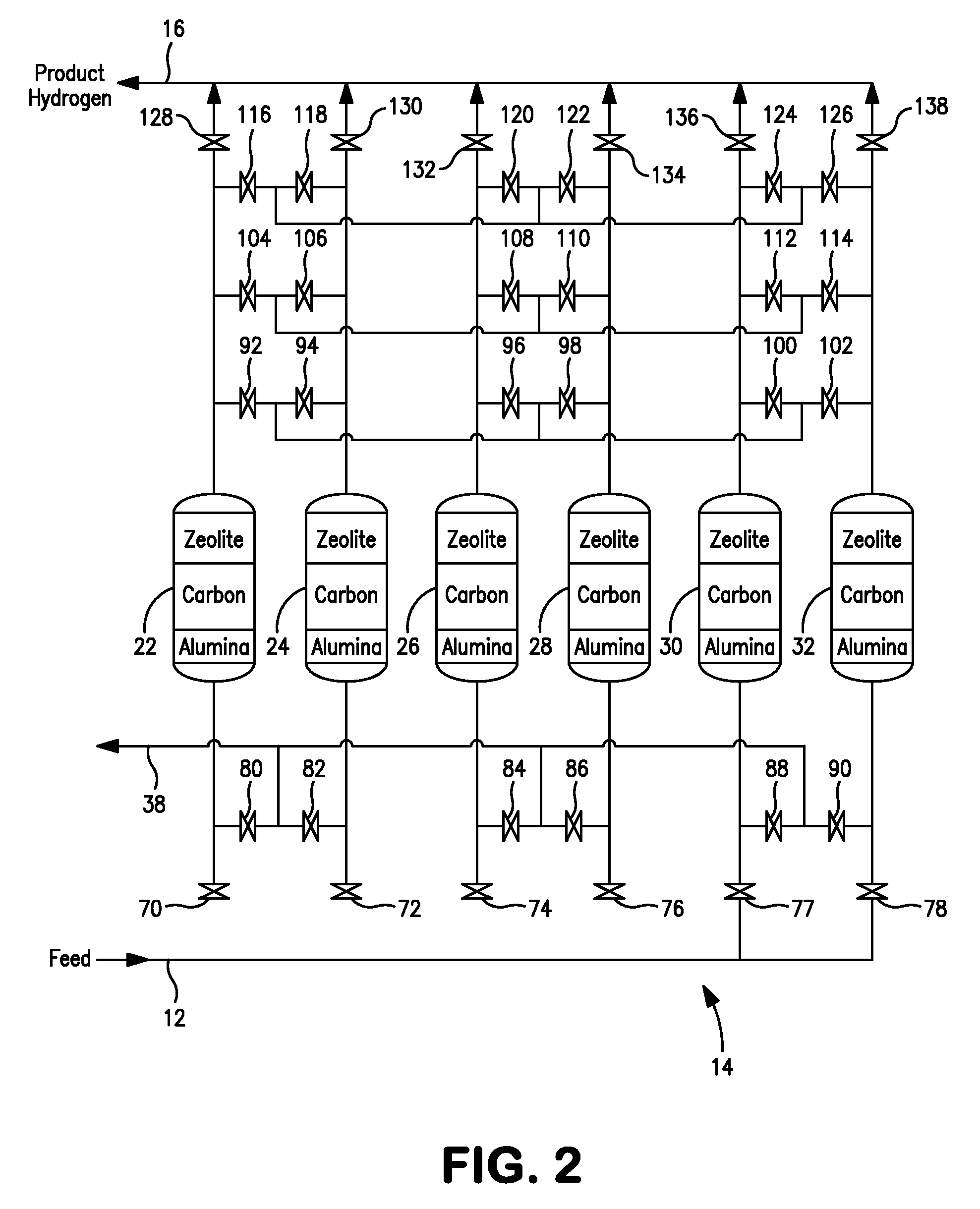
[0035]With reference to FIG. 1, a facility 1, such as a refining facility, is illustrated having a steam methane reformer 10 that produces a feed stream 12 that predominantly contains hydrogen and impurities that range from between about 5 percent and about 25 percent by volume carbon dioxide, less than about 0.5 percent by volume water vapor, less than about 3 percent by volume methane, less than about 1 percent by volume carbon monoxide, less than about 1 percent by volume nitrogen and smaller concentrations of heavier hydrocarbons. Feed stream 12 is introduced into a pressure swing adsorption unit 14 to adsorb the impurities and thus produce a hydrogen product stream 16 that contains the aforementioned impurities in amounts that are less than that allowed by a product specification. It is to be noted that the discussion of facility 1 that follows is not meant to be limiting on the use of the present invention in that the present invention is equally applicable to the control of o...


PUM

PropertyMeasurementUnit
Timeaaaaaaaaaa
Concentrationaaaaaaaaaa
Currentaaaaaaaaaa

Abstract

The present invention provides a method and a control system for controlling an adsorbent bed unit in which an adsorbent bed concentration of an impurity within an adsorbent bed of the adsorbent bed unit is measured. The adsorbent bed concentration is controlled by manipulating the feed cycle time during which an adsorbent bed is adsorbing the impurities to maintain the adsorbent bed concentration at a targeted adsorption bed concentration. The targeted adsorption bed concentration is determined such that the product impurity concentration is maintained at product impurity concentration targets. The method and control system can incorporate a supervisory level of control reactive to product impurity concentration levels and related targets to determine the targeted adsorption bed concentration and a primary level of control that calculates the feed cycle time based upon an error between the measured and targeted adsorption bed concentrations. Proportional integral control can be used for such purposes.

Description

FIELD OF THE INVENTION [0001]The present invention relates to a method of controlling an absorption unit containing one or more adsorption beds to adsorb one or more impurities within a feed stream, thereby to produce a product stream and a controller to accomplish such method. More particularly, the present invention relates to such method and controller in which a concentration of an impurity within an adsorbent bed is sampled and a feed cycle time during which the adsorbent bed is adsorbing impurities is manipulated such that the concentration measured within the bed approaches a target that ensures that the product stream will be produced at a specific purity level.BACKGROUND OF THE INVENTION[0002]There are a variety of processes that employ adsorbents that are capable of adsorbing one or more impurities contained within a feed stream more readily than other impurities within the feed stream to produce a product stream having a lower concentration of the impurities than the feed...

Claims


Application Information

Patent Timeline
IPC IPC(8): B01D53/30
CPCB01D53/0462Y02C10/08B01D53/30B01D2253/102B01D2253/104B01D2253/108B01D2256/16B01D2257/102B01D2257/502B01D2257/504B01D2257/702B01D2259/40009B01D2259/4145C01B3/56C01B2203/0233C01B2203/0283C01B2203/0485B01D53/047Y02C20/40Y02P20/151
Inventor BELANGER, PAUL W.BAKSH, MOHAMED SAFDAR ALLIECHANDRA, PREETIROSINSKI, ANDREW C.
Owner PRAXAIR TECH INC
Why Eureka
Try Eureka