
Methods of making energy efficient cookware

Active Publication Date: 2010-09-30
ENERON
View PDF42 Cites 14 Cited by
  • Summary
  • Abstract
  • Description
  • Claims
  • Application Information

AI Technical Summary

Benefits of technology

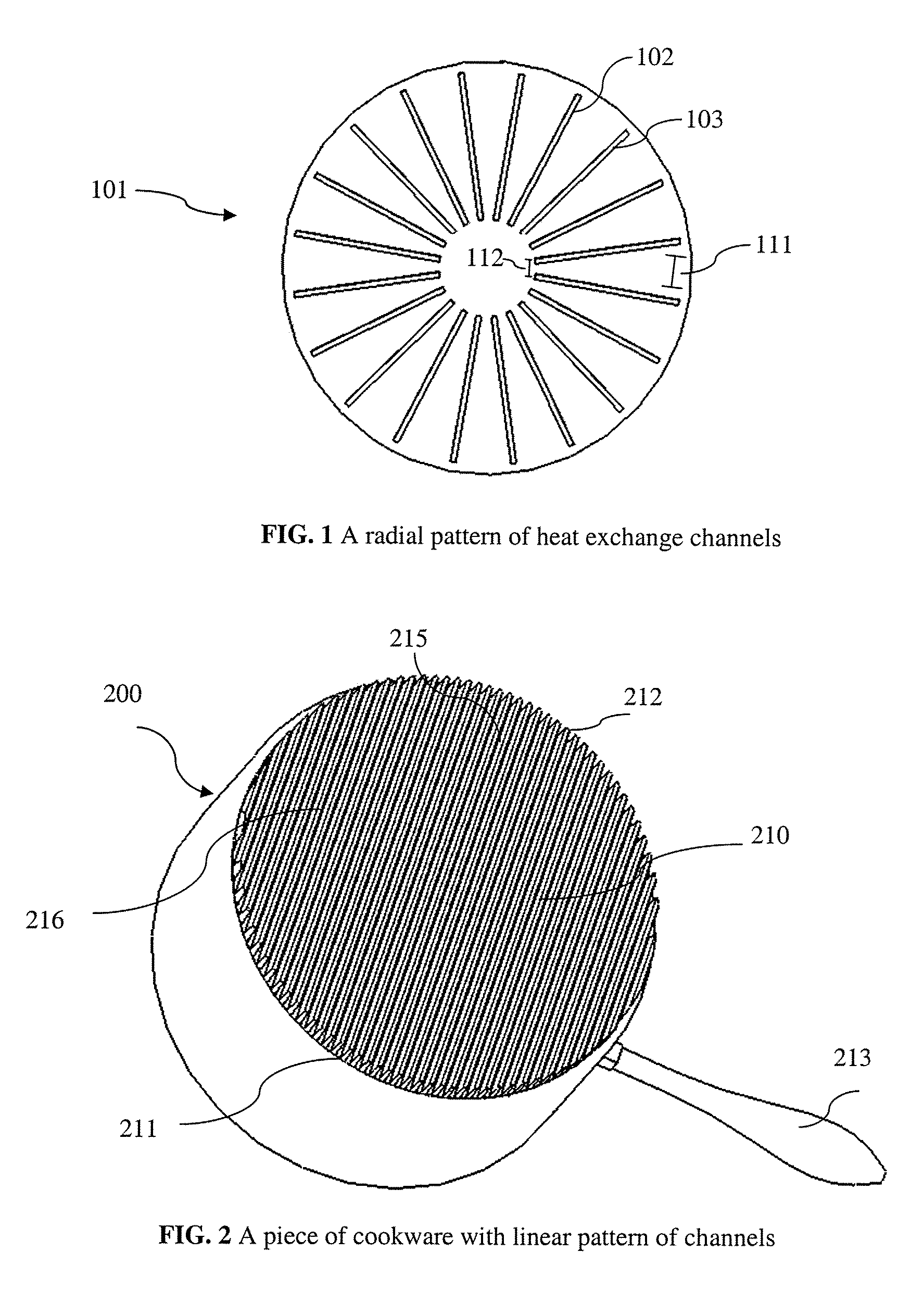
[0012]In operation, the flame guide channel accepts a flame from a burner and guides the flame through the channel towards the perimeter of the cookware base. While flowing through the channel, the perturbation fins generate lateral turbulence in the flame by interfering with an onset of laminar flow. The induced turbulence increases thermal energy transfer from the flame to the cookware base and fins while minimizing the portion of the flame mixed with the ambient air. Such induced turbulence promotes heat conduction from the flame heat through the cookware to food for more efficient cooking. Further, the minimization of the mixing of flame with the air reduces heat loss to the ambient air.
[0021]Also disclosed herein is a metal plate that has heat exchange features. The metal plate can be implemented as the cookware base of a piece of cookware or attached to the cookware base of a piece of cookware. Use of the heat exchange features can improve the efficiency of the piece of cookware.

Problems solved by technology

Thermal energy transfer from combustion sources can be inefficient.
This means that a lot of energy is wasted when cooking.
The inefficiency increases energy bills and produces unnecessary, undesirable CO2 into the environment.
However there has been limited effort to improve the efficiency of the heat-receiving surfaces of cookware.
Other limitations of the related art will become apparent upon a reading of the specification and a study of the drawings.

Method used


Image

  • Methods of making energy efficient cookware
  • Methods of making energy efficient cookware
  • Methods of making energy efficient cookware

Examples


Embodiment Construction

[0039]Although the following detailed description contains many specifics for the purpose of illustration, anyone of ordinary skill in the art will readily appreciate that many variations and alterations to the following exemplary details may be made. One skilled in the relevant art will recognize, however, that the concepts and techniques disclosed herein can be practiced without one or more of the specific details, or in combination with other components, etc. In other instances, well-known implementations or operations are not shown or described in detail to avoid obscuring aspects of various examples disclosed herein.

[0040]In a typical process for cooking food, a piece of cookware holding a medium, such as water, is placed on a gas range having a burner. When ignited, the burner produces a flame that rises up in response to pressure of the gas in the range's supply piping. The buoyancy of the hot air causes the flame to touch the cookware base of the cookware. Thermal energy is ...


PUM

PropertyMeasurementUnit
Thicknessaaaaaaaaaa
Widthaaaaaaaaaa
Heightaaaaaaaaaa

Abstract

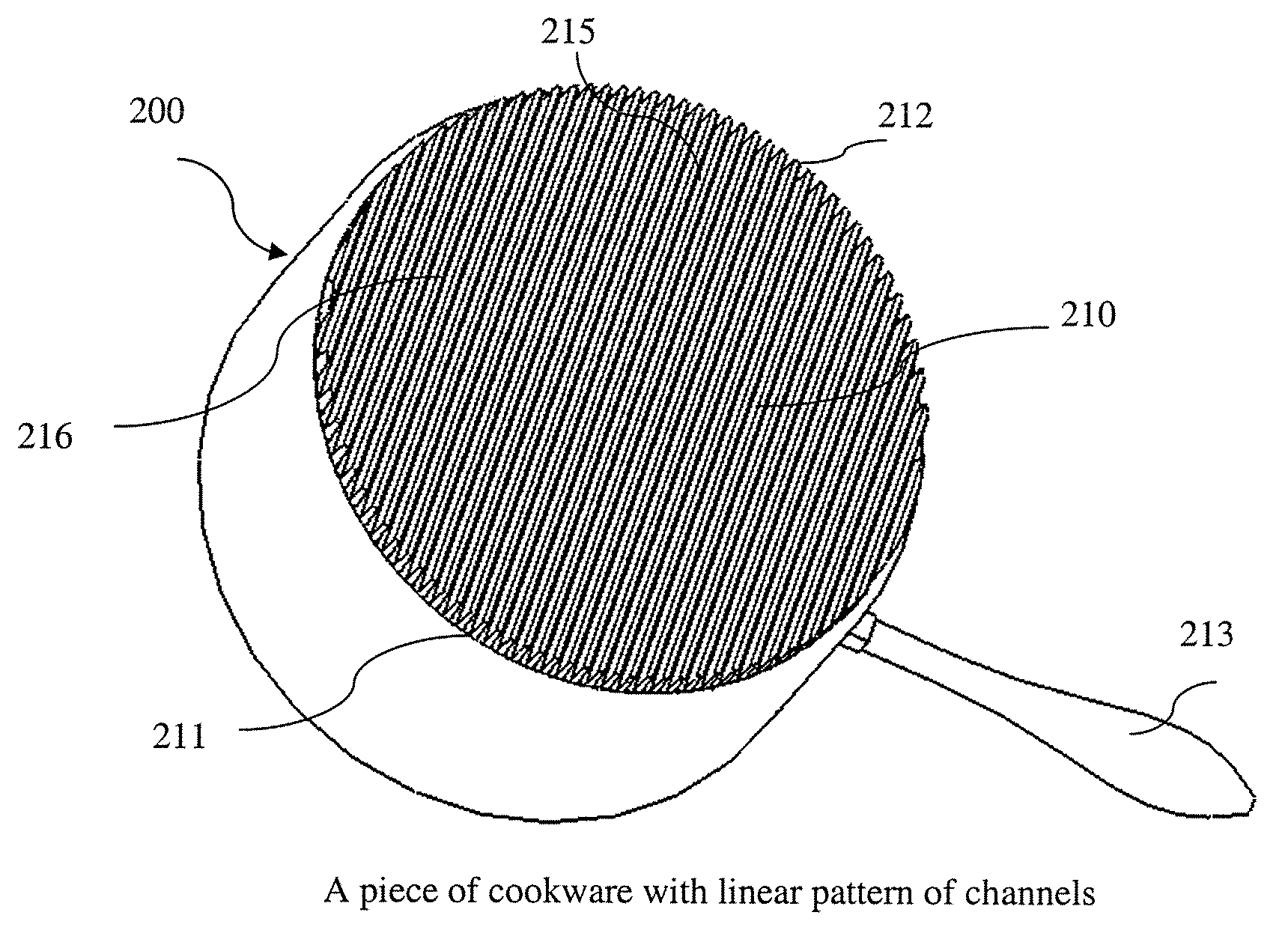
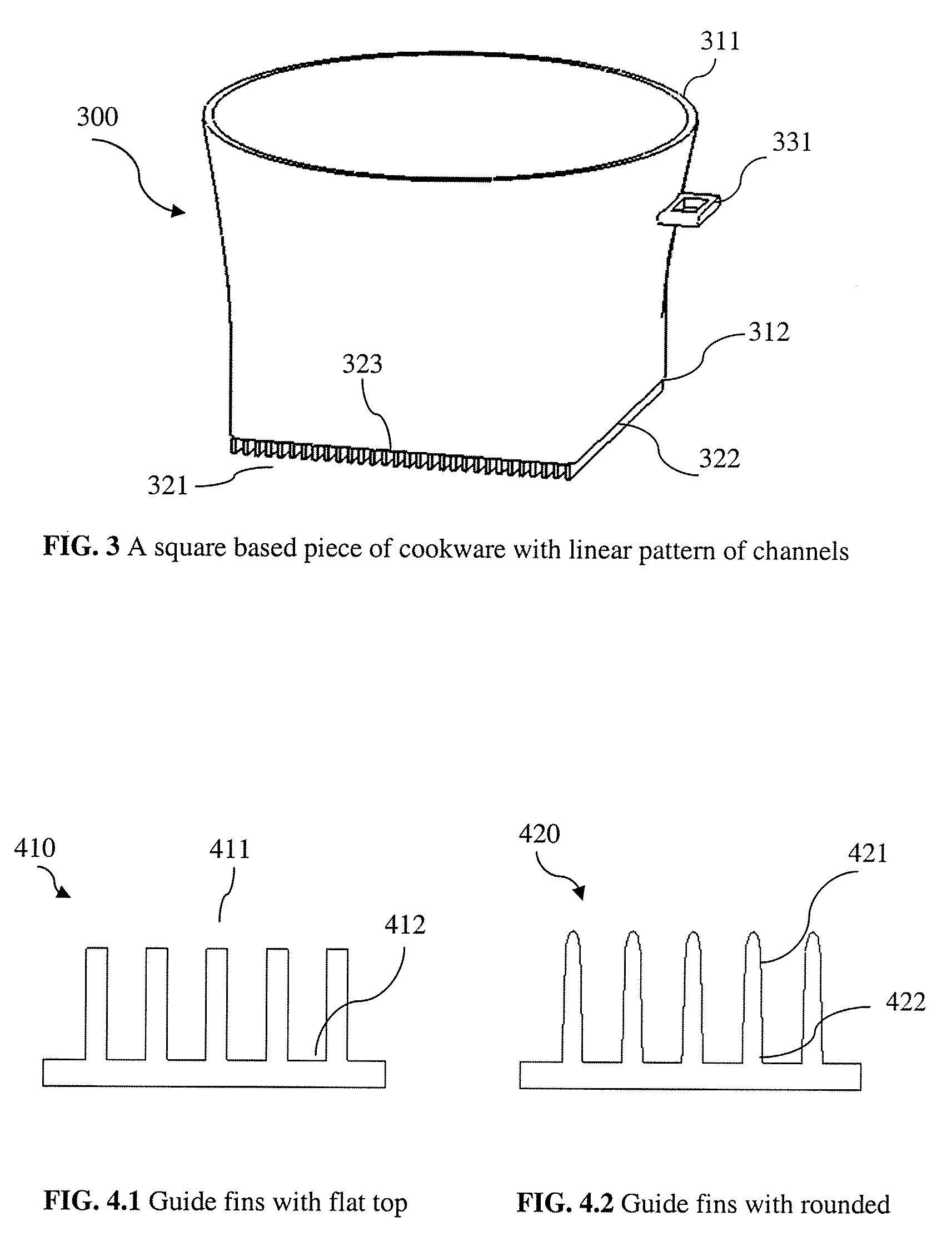
Techniques for designing and creating energy efficient cookware are provided. In accordance with the techniques cookware can include a cookware base having a cooking surface and heating surface. The heating surface can have a pattern of fins forming heat exchange channels. The fins can effectively increase surface area and the channels can guide thermal energy to the perimeter of the cookware base while the fins absorb the thermal energy. The channel fins can improve energy transfer while providing even distribution throughout the cooking surface. The use of fins can also improve the mechanical strength to the cookware. Methods of making the energy efficient cookware are provided. A piece of cookware with a thick base can be provided by casting and by bonding a metal plate to the cookware body. Within the base, heat exchange channels are created by manufacturing processes such as casting or cutting to improve heat transfer.

Description

FIELD OF THE INVENTION[0001]The following disclosure relates to the manufacture of energy efficient cookware. More particularly this paper discusses the manufacture of cookware that efficiently transfers thermal energy from a heating element to a cooking surface.BACKGROUND[0002]Cookware is used to hold and apply heat to food. Exemplary pieces of cookware include a stock pot, a wok, and a frying pan. Although each of these have different shapes, they each include two basic elements: one surface for receiving thermal energy from a heat source, a “heat-receiving surface” and one surface for applying the heat to food, a “cooking surface.”[0003]Thermal energy can be generated from many different sources. Examples include electric and gas ranges. A heat source can generate the thermal energy by, e.g., burning gas, or transferring electricity through a heating coil.[0004]When cooking food, the piece of cookware transfers the thermal energy from the heat-source to a heat-receiving surface. ...

Claims


Application Information

Patent Timeline
IPC IPC(8): B21D53/02B23P23/00
CPCA47J27/022A47J36/02Y10T29/51Y10T29/4935A47J27/002
Inventor HUANG, LEE LISHENG
Owner ENERON
Learn More