
Sighting optics

a technology of optics and front sight, applied in the field of sighting optics, can solve the problems of degrading the aiming process, difficult to place the front sight at the precise position in relation to the target, and inability for users to focus simultaneously on the front sight and the targ

Inactive Publication Date: 2010-09-23
BATTELLE ENERGY ALLIANCE LLC
View PDF12 Cites 5 Cited by
  • Summary
  • Abstract
  • Description
  • Claims
  • Application Information

AI Technical Summary

Benefits of technology

Enables accurate and simultaneous focus on both the front sight and target, enhancing aiming precision while maintaining a compact, lightweight, and rugged design similar to iron sights but with improved aiming capabilities akin to telescopic sights.

Problems solved by technology

However, since the human eye is only capable of focusing at one distance at any given time, it is not possible for a user to focus simultaneously on the front sight and the target.
As a result, the aiming process is degraded.
Because the front sight is out of focus it is difficult to place the front sight at the precise position in relation to the target to produce a hit.

Method used


Image

  • Sighting optics
  • Sighting optics
  • Sighting optics

Examples


Embodiment Construction

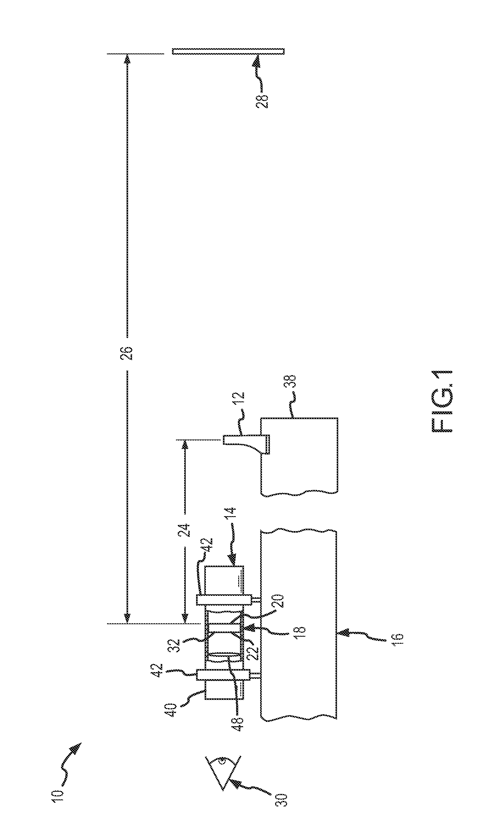
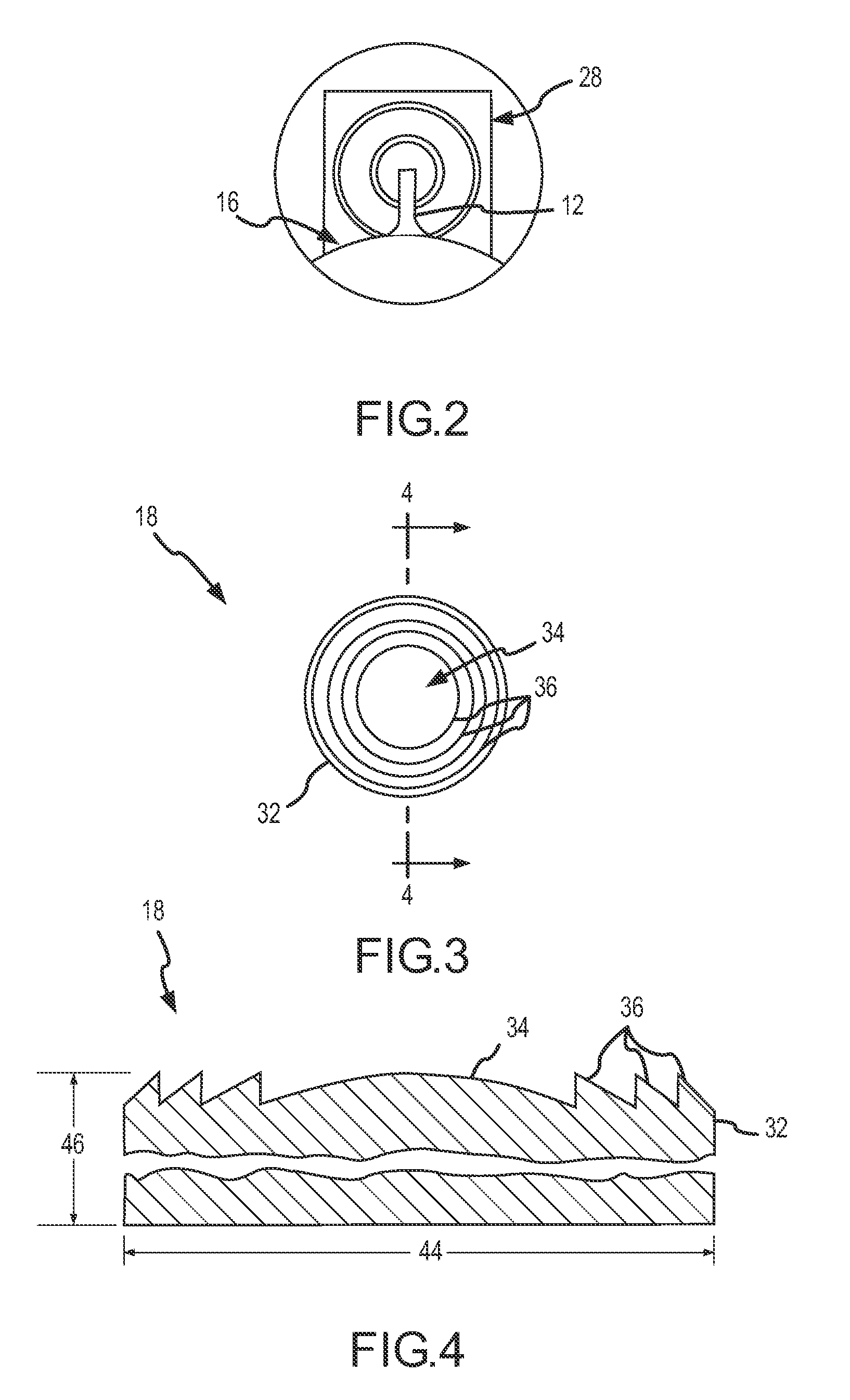
[0020]Sighting optics 10 according to one embodiment of the present invention best seen in FIGS. 1 and 2 and may comprise a front sight 12 and a rear sight 14. Front sight 12 and rear sight 14 may be mounted in spaced-apart relation on a suitable sighting platform, such as a gun barrel 16, although other arrangements are possible, as will be described in further detail below. Rear sight 14 may comprise an optical element 18 having a first focal length and a second focal length. As used herein, the term “focal length” refers to the distance at which an object located on an object side 20 of optical element 18 will be substantially brought into focus (as a virtual image) at a defined location (e.g., to a user's eye 30) on an image side 22 of optical element 18. Because optical element 18 is provided with first and second focal lengths, optical element 18 is capable of bringing into substantially simultaneous focus virtual images of objects located at two different positions (i.e., the...


PUM

PropertyMeasurementUnit
focal lengthaaaaaaaaaa
wavelengthsaaaaaaaaaa

Abstract

One embodiment of sighting optics according to the teachings provided herein may comprise a front sight and a rear sight positioned in spaced-apart relation. The rear sight includes optical element having a first focal length and a second focal length. The first focal length is selected so that it is about equal to a distance separating the optical element and said front sight and the second focal length is selected so that it is about equal to a target distance. The optical element thus brings into simultaneous focus for a user images of the front sight and the target.

Description

CROSS-REFERENCE TO RELATED APPLICATION[0001]This application is a divisional of U.S. patent application Ser. No. 11 / 831,581, filed Jul. 31, 2007 and entitled “Sighting Optics and Methods for Sighting,” pending, the disclosure of which is hereby incorporated herein by this reference in its entirety.GOVERNMENT RIGHTS[0002]This invention was made with government support under Contract Number DE-AC07-05ID14517 awarded by the United States Department of Energy. The government has certain rights in the invention.TECHNICAL FIELD[0003]This invention relates to sighting optics in general and more specifically to sighting systems for weapons.BACKGROUND[0004]Many different types of sighting systems are known in the art and are used to assist in the aiming of a variety of devices, typically those used to launch projectiles, such as firearms and bows, although they are used in other applications as well. Perhaps the simplest and most rugged type of sighting system is the so-called “iron sight,” ...

Claims


Application Information

Patent Timeline
Patent Type & Authority Applications(United States)
IPC IPC(8): G02B27/44F41G1/38G02B25/00
CPCF41G1/01Y10T29/49G02B23/14F41G1/14
Inventor CRANDALL, DAVID LYNN
Owner BATTELLE ENERGY ALLIANCE LLC
Learn More