
Elastic member, slide device using the elastic member, and electric device using the slide device

Inactive Publication Date: 2010-09-23
STRAWBERRY
View PDF11 Cites 18 Cited by
  • Summary
  • Abstract
  • Description
  • Claims
  • Application Information

AI Technical Summary

Benefits of technology

[0021]The present invention addresses the above-identified, and other problems associated with conventional methods and apparatuses. The present invention provides an elastic member of a slide device that may be set to a long sliding distance, avoid a problem of the increase of a space caused by a thickness, easily set the strength of an elastic force of an elastic member, and be excellent in mass productivity and cost by further progressing research and development about this kind of slide device that generates a force in a slide direction by an elastic force of an elastic member; the slide device; and an electric device using the slide device.
[0026]In addition, it may be possible to obtain a very practical slide device that may overcome problems of this kind of slide device in the related art, that is, may avoid a problem of having, a bulky space caused by a thickness and easily make the slide device thin and compact, and may be easily manufactured and be excellent in mass productivity and cost.
[0027]Further, since the connection between ends of the plurality of spring wires of the elastic member and the first and second members of the slide device may be very simply and easily achieved by a simple structure, it may be possible to obtain a slide device that is further excellent in mass productivity and cost.
[0028]Furthermore, since a slide device capable of reliably and easily achieving the above-mentioned advantages is used in the embodiments of the invention, it may be possible to obtain a very practical electric device.

Problems solved by technology

However, the above-mentioned conventional devices have various problems, respectively.
This causes high cost and difficulty in manufacture.
However, considering the stress and load of the torsion spring, there is also a limit on the sliding distance.
Further, since a wire is wound several (three to four) times at a coil-shaped portion that is formed between the both ends of the torsion spring of the torsion spring type slide device, inevitably a space becomes bulky due to the corresponding increase of thickness.
Accordingly, the thickness of the coil-shaped portion of the torsion spring obstructs the disposition of an electronic component such as a FPC, and eventually obstructs the reduction and compactness by the thickness of this kind of electric device.

Method used


Image

  • Elastic member, slide device using the elastic member, and electric device using the slide device
  • Elastic member, slide device using the elastic member, and electric device using the slide device
  • Elastic member, slide device using the elastic member, and electric device using the slide device

Examples


Embodiment Construction

[0039]A specific embodiment of the invention will be described below with reference to drawings.

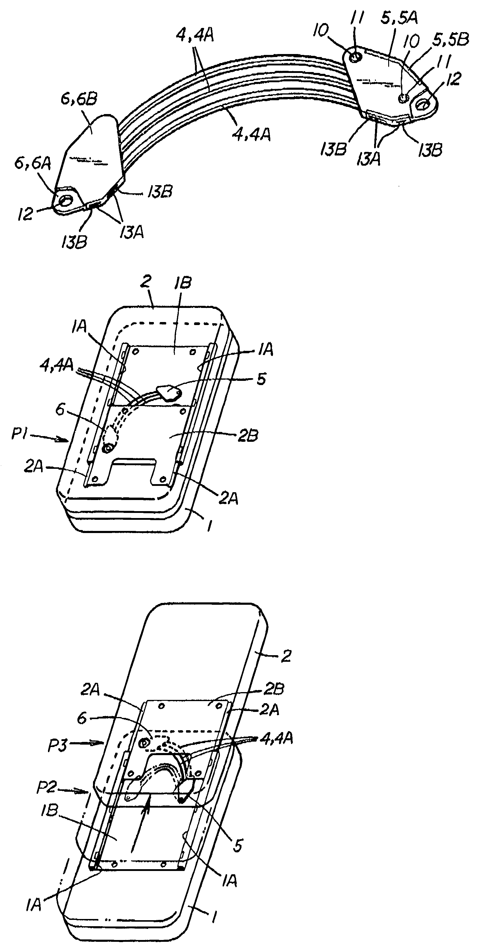
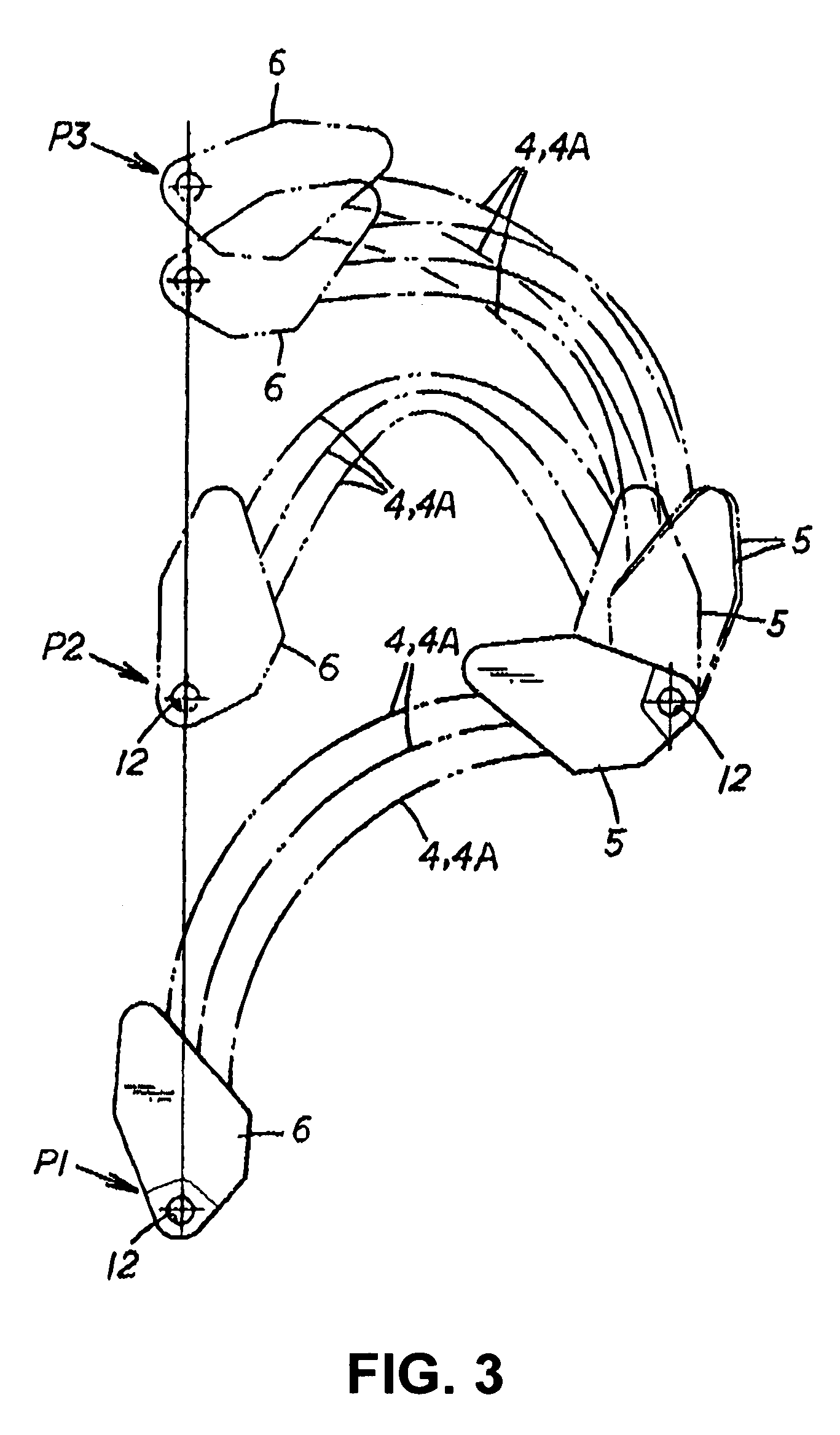
[0040]An elastic member 4 of this embodiment is used between first and second members 1 and 2 of a slide device where the first and second members 1 and 2 are superposed and connected to each other so as to slide in a direction of a superposition surface.

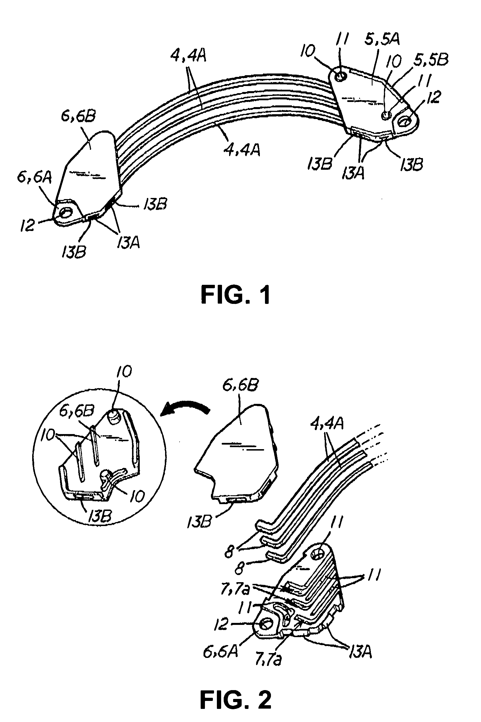
[0041]The elastic member 4 includes a plurality of spring wires 4A that are elastically bent, and first and second connecting sections 5 and 6 that are locked to one ends and the other ends of the spring wires 4A, respectively.

[0042]Each of the spring wires 4A has the shape of a predetermined bent wire including an arcuately bent portion that maybe elastically bent in an arcuate shape, bent or curved locking ends 8 are formed at one ends and the other ends of the spring wires, and both ends of the spring wires 4A including the locking ends 8 are formed in a symmetrical shape.

[0043]The connecting sections 5 and 6 include retaining engageme...


PUM


Abstract

An elastic member used for a slide device includes a plurality of spring wires and first and second connecting sections that are locked to one ends and the other ends of the spring wires, respectively. Locking ends are formed at one ends and the other ends of the spring wires, both ends of the spring wires including the locking ends are formed in a symmetrical shape, the connecting sections include retaining engagement portions that make the plurality of spring wires be engaged with the connecting sections, and the first and second connecting sections are separately formed by forming the same assembling members and the same superposed members. If the assembling members are fixed to the superposed members while the ends of the spring wires are fitted to the grooves of the retaining engagement portions and the superposed members are assembled to be superposed on the assembling members, the ends of the plurality of spring wires are disposed at predetermined intervals and retained by the connecting sections.

Description

BACKGROUND[0001]1. Technical Field[0002]The present invention relates to an elastic member, a slide device using the elastic member, and an electric device such as a mobile phone or a mobile device using the slide device.[0003]2. Related Art[0004]In the past, for example, there has been a slide mobile phone where an operating section including numerical keys and function keys are provided on an upper surface of the main body unit, a display section such as a liquid crystal panel for performing predetermined display is provided on an upper surface of a superposed unit superposed on the main body unit, and the main body unit and the superposed unit are moved relative to each other in a longitudinal direction.[0005]The slide mobile phone has a structure where guide rails serving as slide guides are provided at the left and right portions on the superposed unit with a gap therebetween, the main body unit is provided with a slide portion that is slidably engaged with the left and right g...

Claims


Application Information

Patent Timeline
IPC IPC(8): F16F1/18
CPCF16F3/023H02G11/003H04M1/0237
Inventor KUBOTA, NORIAKI
Owner STRAWBERRY
Learn More