Enclosure member and multi-link conveyor chain
a conveyor chain and locking member technology, applied in the direction of conveyors, transportation and packaging, etc., can solve the problems of multi-link conveyor chain collapse, pin head wear and eventually shear off, and elongated pin dislodge,
- Summary
- Abstract
- Description
- Claims
- Application Information
AI Technical Summary
Benefits of technology
Problems solved by technology
Method used
Image
Examples
first embodiment
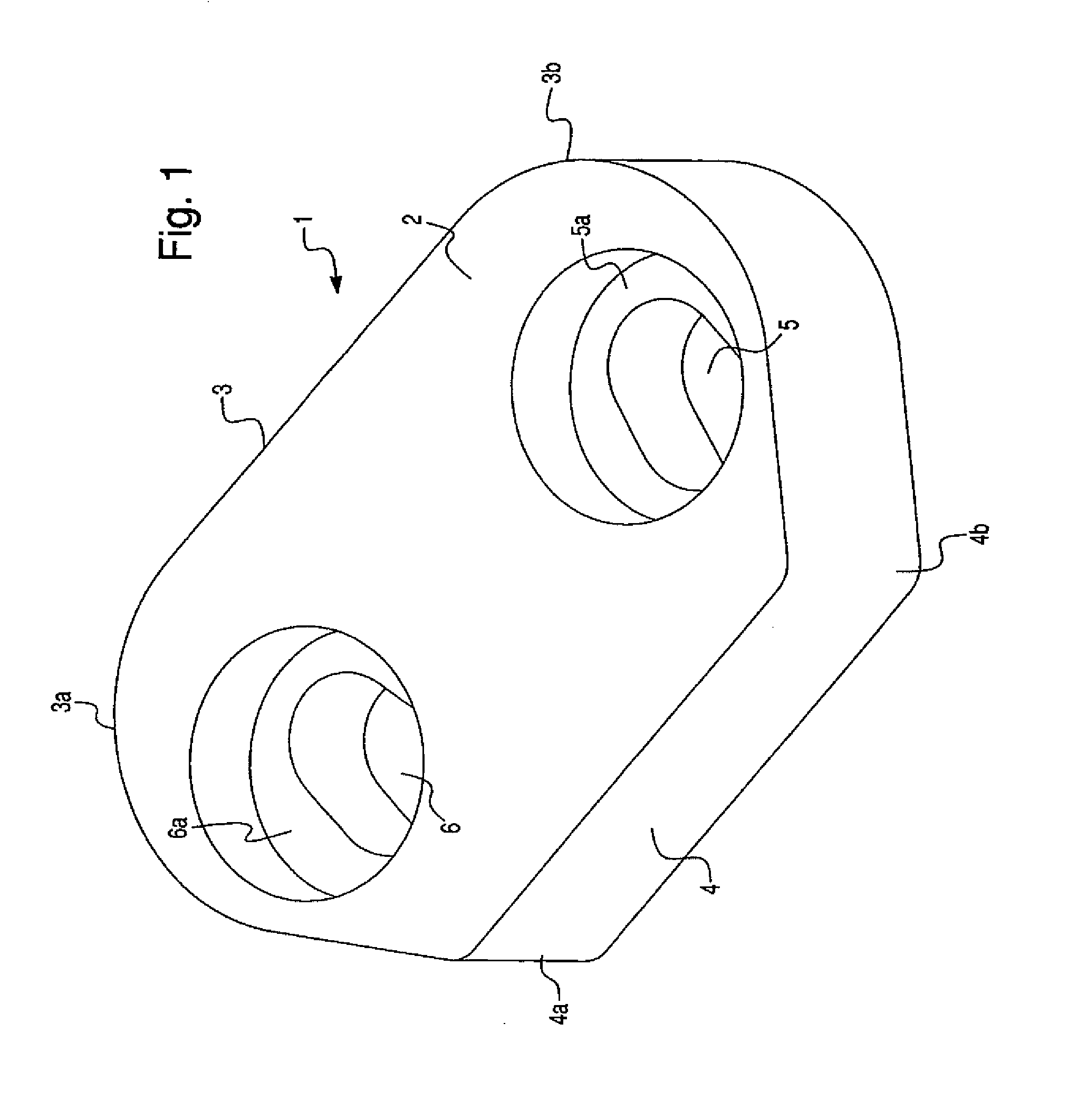
[0057]FIG. 1 illustrates the enclosure member of the invention designated generally by reference numeral 1. The enclosure member 1 includes a trapezoidal main body 2 having a long side 3 parallel to a closed short side 4. The corners 3a and 3b of the long side 3 are rounded off (and to a lesser extent so are the corners 4a and 4b of the short side 4). The main body 2 defines a first non-circular aperture 5 and a second non-circular aperture 6, each of which are elliptical and provided with a cylindrical counterbore 5a and 6a respectively. The counterbores 5a and 6a are non-tapered.
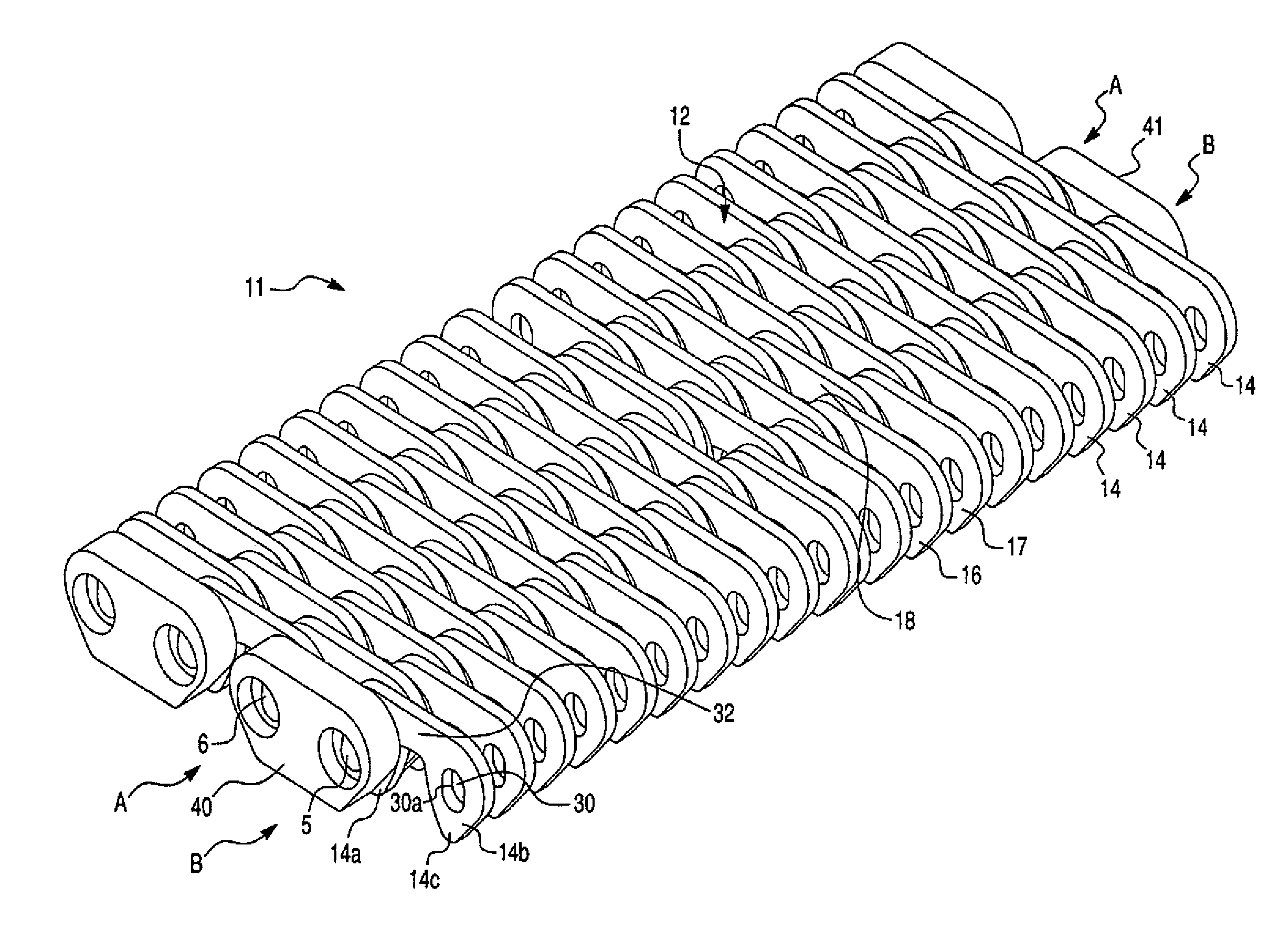
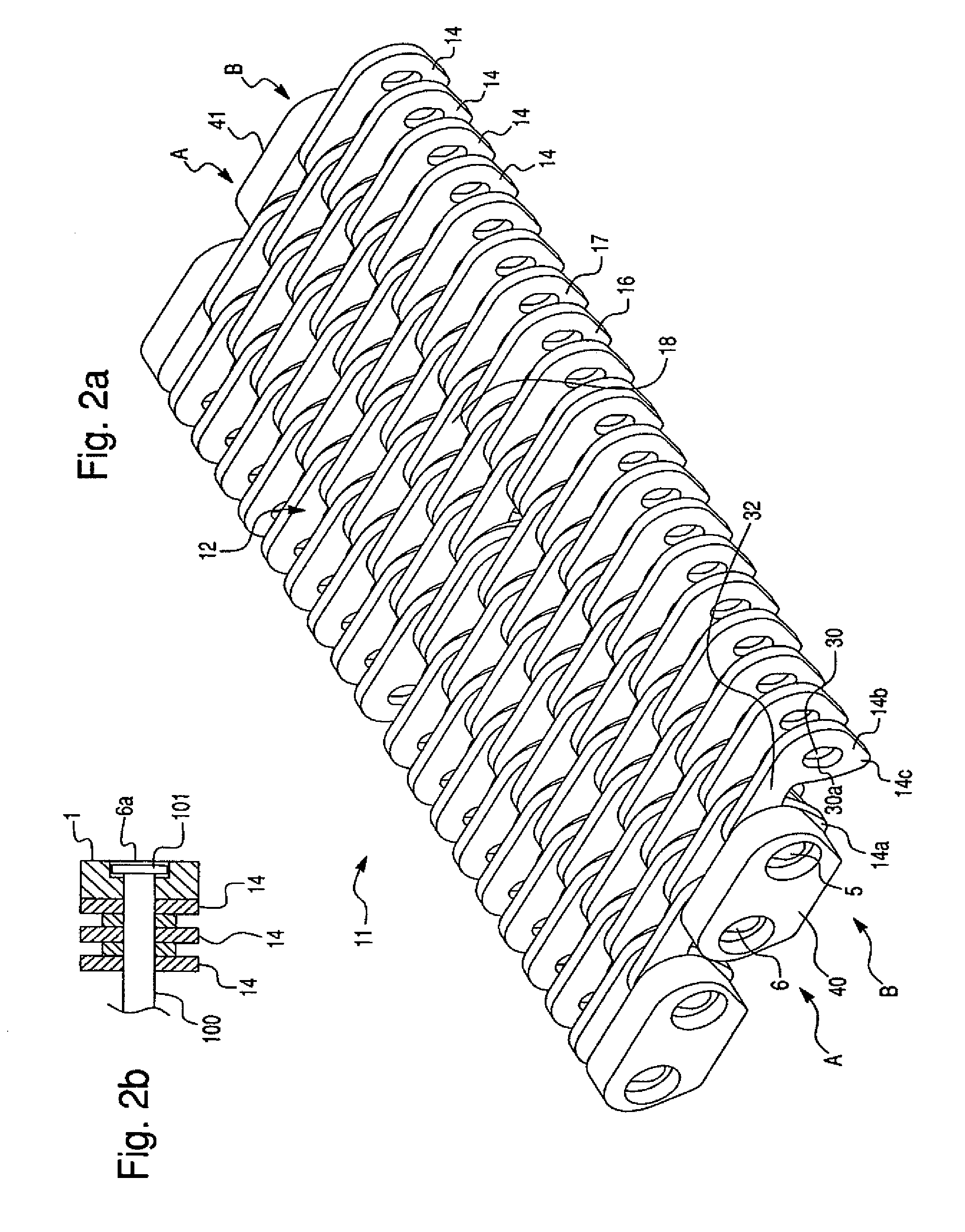
[0058]FIG. 2a illustrates in partial view an embodiment of the multi-link conveyor chain of the invention designated generally by reference numeral 11. For the sake of clarity, the elongate pins are omitted from FIG. 2a.
[0059]The multi-link conveyor chain 11 provides a flat surface 12 upon which may be carried articles such as glass bottles to a processing station. The multi-link conveyor chain 11 compris...
second embodiment
[0062]FIGS. 3a and 3b illustrate the enclosure member of the invention designated generally by reference numeral 31. The enclosure member 31 is used in side guide chains. The enclosure member 31 comprises a trapezoidal main body 32 having a long side 33 parallel to a closed short side 34. The corners 33a and 33b of the long side 33 are rounded off (and to a lesser extent so are the corners 34a and 34b of the short side 34). The rear face of the main body 32 is partially recessed with a substantially U-shaped recess 432. The main body 32 defines a first non-circular aperture 35 and a second non-circular aperture 36, each of which are elliptical and provided with a cylindrical counterbore 35a and 36a respectively. The counterbores 35a and 36a are non-tapered.
third embodiment
[0063]FIG. 4 illustrates the enclosure member of the invention designated generally by reference numeral 41. The enclosure member 41 is used in center guide chains. The enclosure member 41 comprises a trapezoidal main body 42 having a long side 43 parallel to an open short side 44. The open short side is defined by a deep U-shaped cut-away portion 47. The corners 43a and 43b of the long side 43 are rounded off (and to a lesser extent so are the corners 44a and 44b of the short side 44). The main body 42 defines a first non-circular aperture 45 and a second non-circular aperture 46, each of which are elliptical and provided with a cylindrical counterbore 45a and 46a respectively. The counterbores 45a and 46a are non-tapered.
PUM
 Abstract
Description
Claims
Application Information
 - R&D Engineer
- R&D Manager
- IP Professional
- Industry Leading Data Capabilities
- Powerful AI technology
- Patent DNA Extraction
Browse by: Latest US Patents, China's latest patents, Technical Efficacy Thesaurus, Application Domain, Technology Topic, Popular Technical Reports.
© 2024 PatSnap. All rights reserved.Legal|Privacy policy|Modern Slavery Act Transparency Statement|Sitemap|About US| Contact US: help@patsnap.com


