
Bundle tie with head dampener

a technology of dampener and bundle, applied in the field of bundle ties, can solve problems such as damage to bundles, and achieve the effect of preventing damage to bundles and preventing elongation of articles

Active Publication Date: 2010-09-23
HELLERMANNTYTON CORP
View PDF46 Cites 53 Cited by
  • Summary
  • Abstract
  • Description
  • Claims
  • Application Information

AI Technical Summary

Benefits of technology

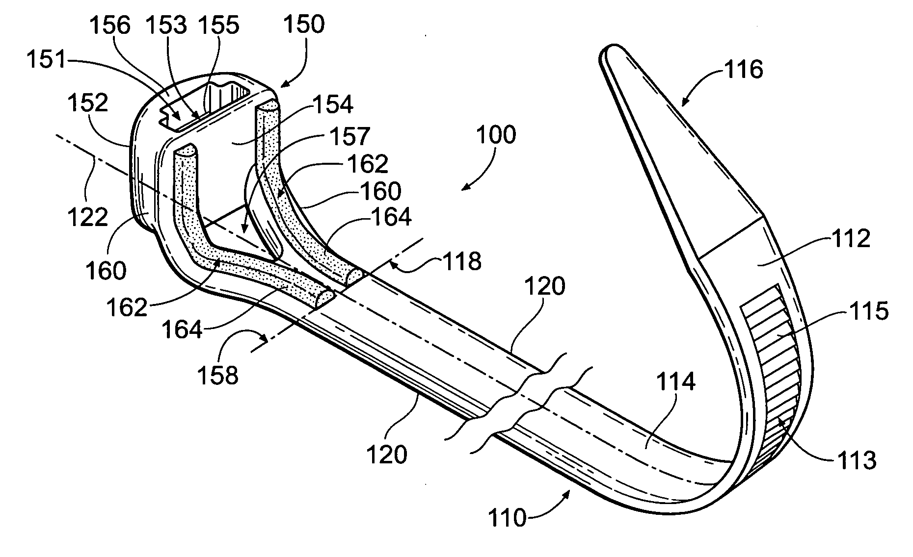
[0006]A device according to the present invention provides a bundle tie having a head dampener to assist in preventing damages to a tied bundle and further to assist in preventing an elongate article, or a plurality of elongate articles, from sliding within a bundle tie loop.

Problems solved by technology

Regardless of the manner in which a tie head is oriented on a tie, it has been observed that certain forces imparted by a tie head onto the bundle being secured may be damaging to the bundle.

Method used


Image

  • Bundle tie with head dampener
  • Bundle tie with head dampener
  • Bundle tie with head dampener

Examples


Embodiment Construction

[0044]Although the disclosure hereof is detailed and exact to enable those skilled in the art to practice the invention, the physical embodiments herein disclosed merely exemplify the invention which may be embodied in other specific structures. While the preferred embodiment has been described, the details may be changed without departing from the invention, which is defined by the claims.

[0045]Turning now to the Figures, FIG. 1A provides a first embodiment 100 of a bundle tie according to the present invention. The tie 100 generally comprises a substantially flat tie strap 110 having a strap outer surface 112 and a strap bundle surface 114 generally opposed from the strap outer surface 112, extending between a first strap end 116 and a second strap end 118. The tie strap 110 includes two lateral strap edges 120, each edge being situated preferably substantially parallel to and equidistant from a central longitudinal axis 122, preferably along at least a majority of the length 111 ...


PUM

PropertyMeasurementUnit
Lengthaaaaaaaaaa
Forceaaaaaaaaaa

Abstract

An apparatus according to the present invention provides a bundle tie including a head dampener. The tie generally comprises a strap and a tie head coupled to the strap. The tie head is adapted to engage a free end of the strap, thereby forming a loop, which may be formed or placed about one or a bundle of elongate articles such as conduit, wires, cables, ropes, and pipes, for example. The tie head is provided with a head dampener which serves to cushion what otherwise may be damaging force placed upon the one or more elongate articles by the tie head. The dampener may also serve to limit movement of the one or more elongate articles through the loop formed by the tie.

Description

BACKGROUND OF THE INVENTION[0001]The present invention is directed generally to bundle ties, and more specifically to a bundle tie having an improved bundle-engaging surface.[0002]Bundle ties, sometimes referred to as cable ties, are generally well known in the art. A typical bundle tie includes a relatively flat strap having a free first end and a tie head coupled to a second end. The tie head generally includes a strap engaging means, which may be provided as an aperture through the tie head and a locking pawl situated on or within the head, the pawl adapted to engage one or more serrations provided on an engaging surface of the strap. When the strap is inserted into the aperture in the tie head and the pawl engages the serrations, the tie generally forms a tie loop.[0003]Prior tie heads have been coupled to a tie strap generally in two orientations: first, normal entry tie heads include an aperture through the tie head that is formed substantially perpendicular to the strap in it...

Claims


Application Information

Patent Timeline
IPC IPC(8): B65D63/10B65D63/00
CPCB65D63/10F16L55/035Y10T24/141B29C45/1615Y10T24/1498B65D63/1063F16L3/233B29C45/1635Y10T24/14B65D63/1027B65D2563/108F16L55/02F16L57/00
Inventor DYER, EDWARD P.
Owner HELLERMANNTYTON CORP
Learn More