
Apparatus & associated methodology of generating a multi-core communications topology

a communication topology and multi-core processor technology, applied in the direction of multi-programming arrangements, program control, instruments, etc., can solve the problems of limited ability to keep pace, increase in complexity and resource consumption of software, and corresponding demand for hardware platforms

Active Publication Date: 2010-09-16
POLYCORE SOFTWARE
View PDF22 Cites 58 Cited by
  • Summary
  • Abstract
  • Description
  • Claims
  • Application Information

AI Technical Summary

Benefits of technology

"The patent describes an invention that allows for the creation of a communication topology for a multi-core computer. This topology is generated using an application programming device and a dedicated library. The topology includes a set number of nodes that map to the available cores of the computer. The properties of each node are specified, and communication between them is specified using the library. The output file is validated and processed to create a multi-core communication capable executable application program interface (API) for the computer. The technical effect of this invention is the improved performance and efficiency of multi-core computers by optimizing communication between their cores."

Problems solved by technology

As software increases in complexity and resource consumption, a corresponding demand on hardware platforms is created.
In answering this demand, single-core processors and the performance imperative of Moore's Law, have limited the ability to keep pace by corresponding increases in processing power (i.e., via increasing clock speeds).
Such application software will not automatically run faster on an embedded multi-core computer; in fact it may not run at all.
This may be the case even if the software is multi-threaded, as in a single processor the threads will run sequentially whereas in a multi-core computer they may run concurrently, exposing synchronization problems not discovered in the single processor case.
Programming multithreaded code often requires complex coordination of threads and can easily introduce bugs that are difficult to find due to the interleaving of processing on data shared between threads.

Method used


Image

  • Apparatus & associated methodology of generating a multi-core communications topology
  • Apparatus & associated methodology of generating a multi-core communications topology
  • Apparatus & associated methodology of generating a multi-core communications topology

Examples


Embodiment Construction

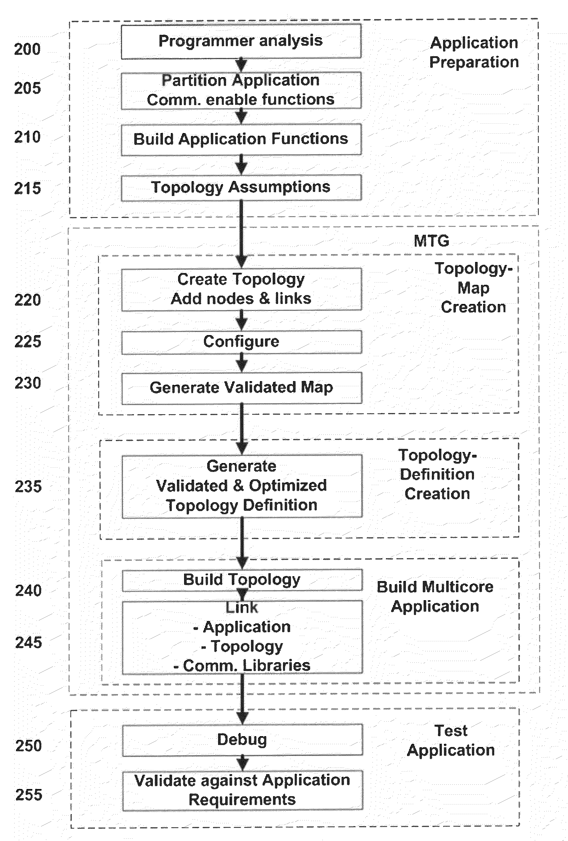
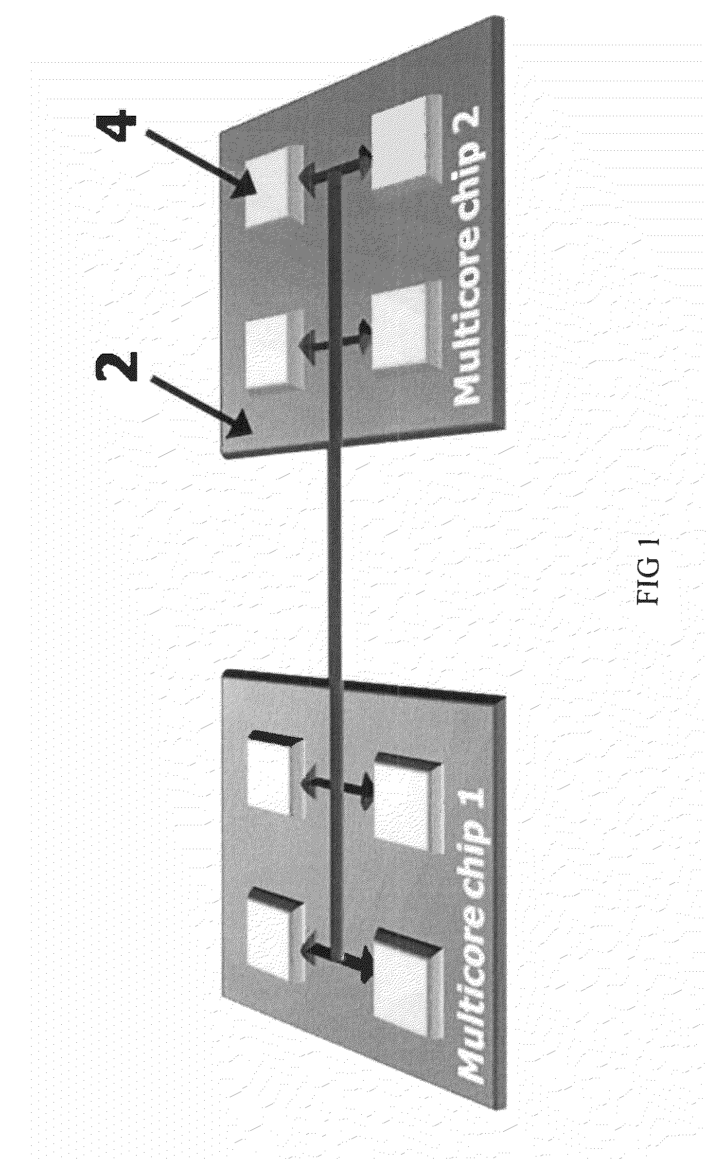
[0022]The advancements in the art described herein employ a “Multi-core Communications Topology Generator” (MCTG) to generate, as the name implies, a multi-core communication topology having a predefined number of nodes to be distributed onto the cores of a multi-core processor computer using an Extensible Markup Language, for example, (XML).

[0023]Certain terminology used in the following description is for convenience only and is not limiting. The term “multi-core processor computer” is used herein to refer to a computer running two or more independent cores integrated into a single silicon die, or having two or more cores assembled in an integrated package, or on one or more printed circuit boards (PCB's). Exemplary multi-core processor computers commercially available include the PowerPC® and Cell Processor from IBM of Armonk, N.Y., Xeon® from Intel of Santa Clara, Calif., and the OMAP® from Texas Instruments of Dallas, Tex. Likewise, a “core” is used herein to refer to a central...


PUM


Abstract

An apparatus and associated method of generating a multi-core communication topology. The topology corresponding to a predetermined number of cores of a multi-core computer, is generated with an application programming device. A number of nodes are described for mapping to the predetermined number of available cores of the multi-core communication topology. Properties of each of the number of nodes are specified. Communication between each of the nodes of the multi-core communication topology is specified using a dedicated multi-core communication library of an electronic memory of the application programming device. A validated output file is generated for the multi-core topology at the application programming device. The output file to is processed to generate a multi-core communication capable executable application program interface (API) for the multi-core computer.

Description

BACKGROUND OF THE INVENTIVE FIELD[0001]The presently described advancements relate to a multi-core processor interface function and topology, and, more particularly, to a multi-core processor interface leveraging a generated topology for providing decreased energy utilization and increased operational speed, and associated methodology.[0002]The “background” description provided herein is for the purpose of generally presenting the context of the inventive field. Work of the presently named inventors, to the extent described in this section, as well as aspects of the background description which may not otherwise qualify as prior art at the time of filing, are neither expressly or impliedly admitted as prior art, but instead, provided in the spirit of teaching the overall context of the advancements claimed herein.[0003]As software increases in complexity and resource consumption, a corresponding demand on hardware platforms is created. In answering this demand, single-core processor...

Claims


Application Information

Patent Timeline
Patent Type & Authority Applications(United States)
IPC IPC(8): G06F9/46G06F3/048
CPCG06F9/5066
Inventor BREHMER, SVENABUELATA, TAMERSTOICA, LULIAN
Owner POLYCORE SOFTWARE
Learn More