
Garment for measuring physiological signals and method of fabricating the same

a physiological signal and fabric technology, applied in knitting, diagnostic recording/measuring, applications, etc., can solve the problems of distorted signals or noises, badly deformed garments, etc., and achieve the effect of stably measuring the distortion and noise of detected physiological signals and keeping the distortion and noise below a low level

Inactive Publication Date: 2010-09-16
ELECTRONICS & TELECOMM RES INST
View PDF6 Cites 330 Cited by
  • Summary
  • Abstract
  • Description
  • Claims
  • Application Information

AI Technical Summary

Benefits of technology

[0037]As described above, according to the present invention, although the physiological signal measuring garment can be folded and / or stretched when a user takes exercise, distortion and noise of detected physiological signals can be kept below a low level. That is, physiological signals of the user can be stably measured over a long time period during everyday life activities or sport activities of the user, such as running and gymnastics. Therefore, the physiological signal measuring garment is useful for healthcare.
[0038]Furthermore, since the electrode sensor of the physiological signal measuring garment can be adjusted according to the kinds of physiological signals to be measured, various physiological signals can be measured, such as 1-chanel or 3-chanel electrocardiogram signals, respiratory waveform signals, and belly or left / right body fat signals. In addition, since the electrode sensors and the measurement unit can be attached to any portions of the physiological signal measuring garment as long as the user does not feel uncomfortable, the physiological signal measuring garment can be flexibly designed.

Problems solved by technology

If the signal connection line has not elastic, the garment can be badly deformed due to an inelastic signal connection line when the person with the garment moves or takes exercise.
Moreover, distorted signals or noises can be generated.

Method used

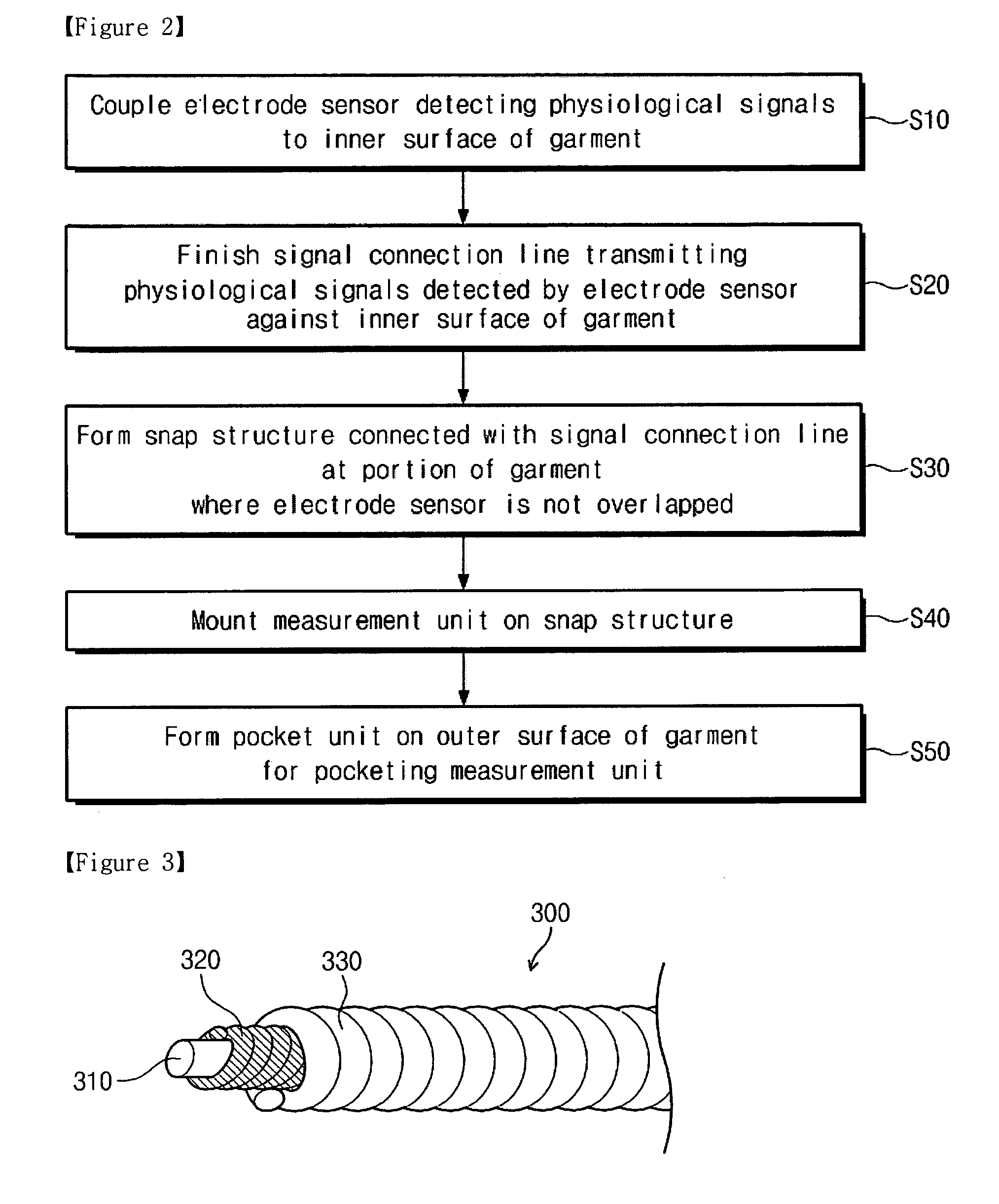

Image

  • Garment for measuring physiological signals and method of fabricating the same
  • Garment for measuring physiological signals and method of fabricating the same
  • Garment for measuring physiological signals and method of fabricating the same

Examples


Embodiment Construction

[0054]Preferred embodiments of the present invention will be described below in more detail with reference to the accompanying drawings. The present invention may, however, be embodied in different forms and should not be construed as limited to the embodiments set forth herein. Rather, these embodiments are provided so that this disclosure will be thorough and complete, and will fully convey the scope of the present invention to those skilled in the art. In the figures, the dimensions of layers and regions are exaggerated for clarity of illustration, and like reference numerals refer to like elements throughout.

[0055]Hereinafter, an exemplary embodiment of the present invention will be described with the accompanying drawings.

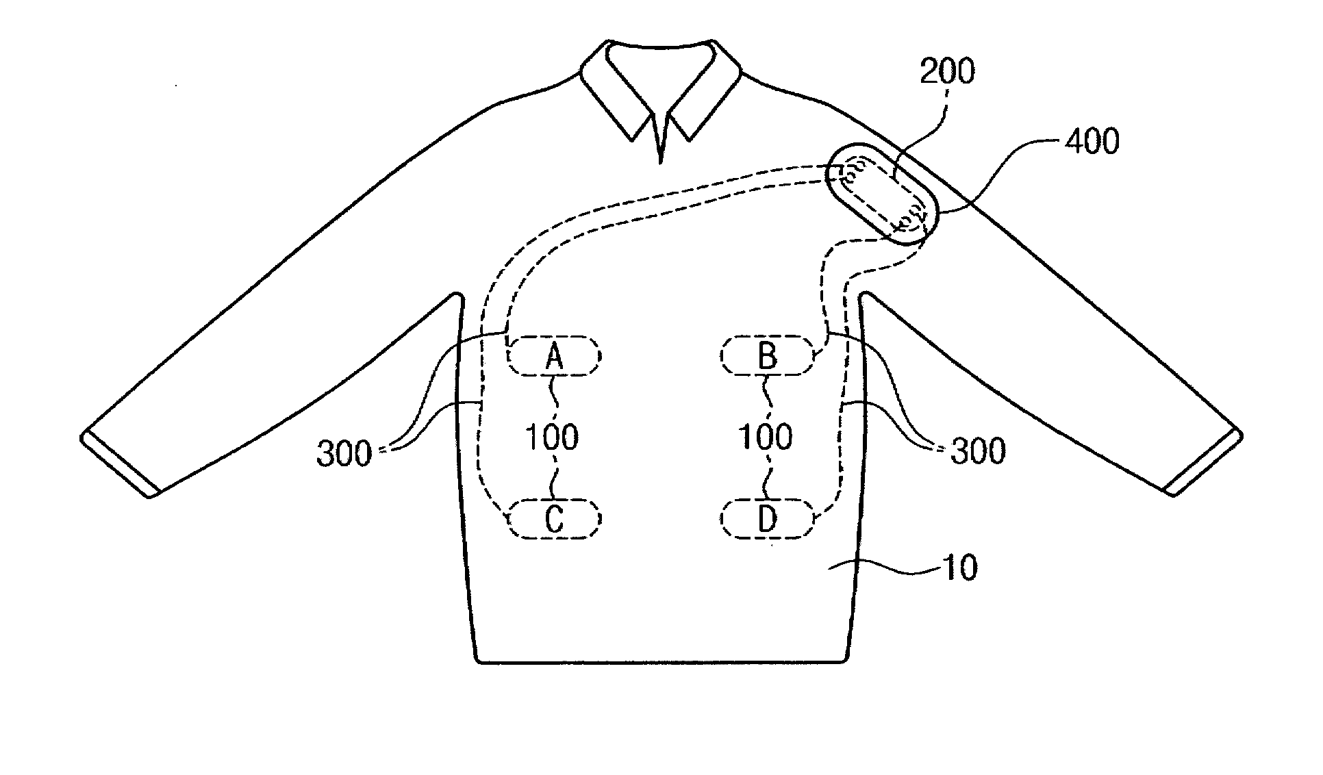
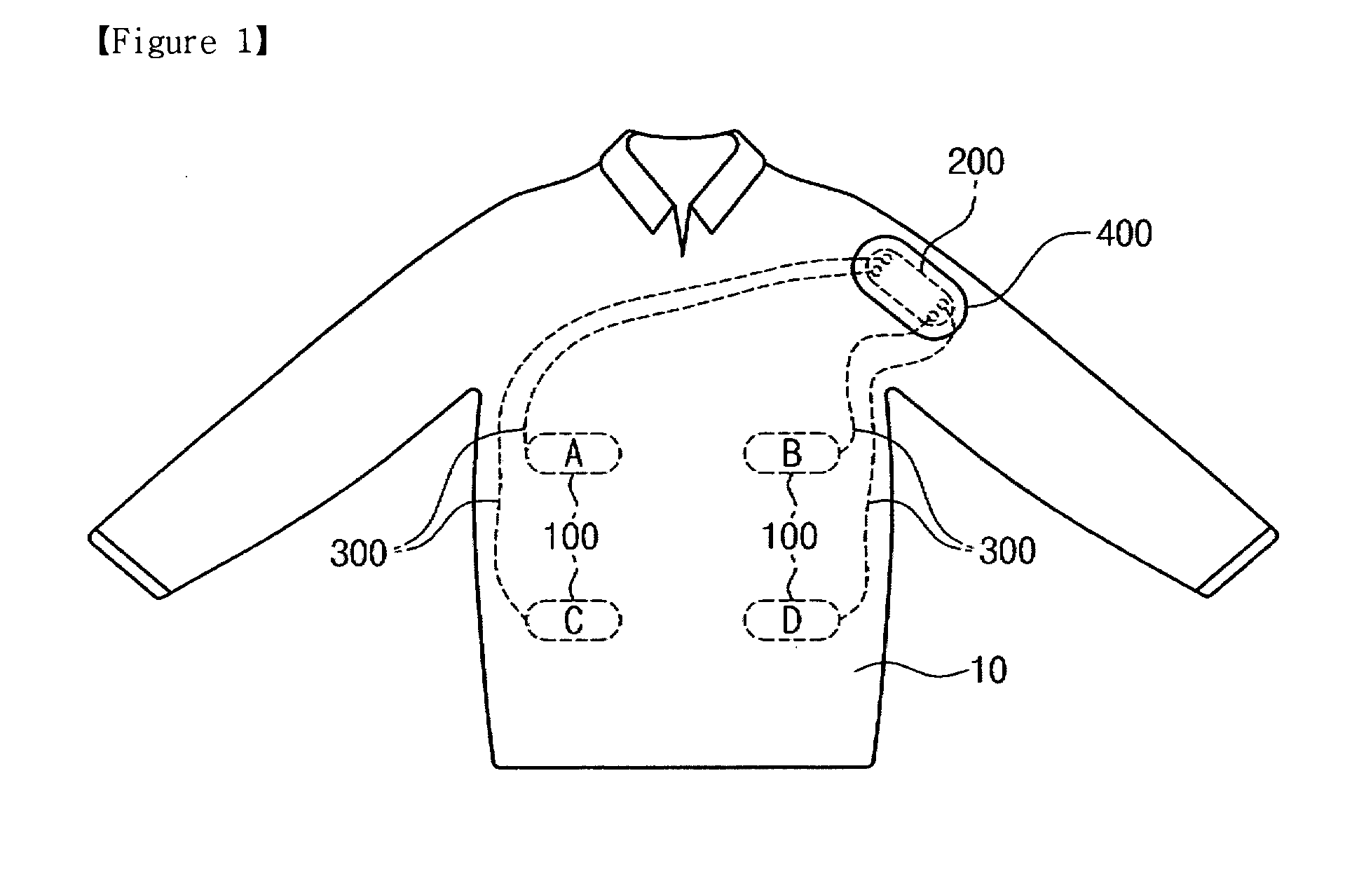
[0056]FIG. 1 is a schematic view illustrating a physiological signal measuring garment according to an embodiment of the present invention.

[0057]Referring to FIG. 1, the physiological signal measuring garment may include a garment 10, electrode sensor units 10...


PUM


Abstract

Provided is a garment for measuring physiological signals. The garment includes at least one electrode sensor, a signal connection line, a snap structure, and a measurement unit. The electrode sensor is coupled to an inner surface of the garment to make contact with a skin for detecting physiological signals. The signal connection line transmits the physiological signals detected by the electrode sensor. The signal connection line is finished against the inner surface of the garment. The snap structure is coupled to a portion of the garment where the electrode sensor is not overlapped and is electrically connected to the signal connection line. The measurement unit is mounted on the snap structure for measuring the physiological signals. The signal connection line has elasticity.

Description

TECHNICAL FIELD[0001]The present invention disclosed herein relates to a garment for measuring physiological signals and a method of fabricating the garment, and more particularly, to a garment for stably measuring physiological signals even when a user moves or takes vigorous exercise, and a method of fabricating the garment.[0002]The present invention has been derived from research undertaken as a part of IT R & D program of the Ministry of Information and Communication and Institution of Information Technology Association (MIC / IITA) [2006-S-007-02], Ubiquitous health monitoring module and system development.BACKGROUND ART[0003]Recent attempts for ubiquitous-healthcare include attaching sensors to a garment of a person to obtain information about health conditions of the person. The sensors should be securely kept in contact with a skin of the person to measure physiological signals for obtaining information about the health conditions of the person, such as electrocardiograms, pu...

Claims


Application Information

Patent Timeline
IPC IPC(8): A61B5/04D05B23/00D04B1/24
CPCA61B5/0402A61B5/6804A61B5/0537A61B5/04085A61B5/282A61B5/318A41D1/02A61B5/00A61B5/33
Inventor SHIN, SEUNG-CHULJANG, YONG-WONLEE, IN-BUMKIM, SEUNG-HWANPARK, SEON-HEE
Owner ELECTRONICS & TELECOMM RES INST
Learn More