
Neurological device

a neurologic and neurological technology, applied in the field of neurologic rehabilitation devices, can solve the problems of not being able to extend their wrist or fingers to grasp objects, unable to use cuffs when practical, and no known prior art is neurological

Inactive Publication Date: 2010-09-16
SAEBO
View PDF9 Cites 76 Cited by
  • Summary
  • Abstract
  • Description
  • Claims
  • Application Information

AI Technical Summary

Benefits of technology

[0007]The present invention recognizes and addresses disadvantages of prior art constructions and methods, and it is an object of the present invention to provide an improved wheel slip monitoring system. This and other objects may be achieved by a neurological device comprising a forearm support that is configured to be releasably attached to a user's arm, at least one finger sleeve adapted to be releasably attached to at least one finger, at least one tensor strut having a first end releasably coupled to the at least one finger sleeve and an opposite second end coupled to the forearm support, at least one sensor coupled to at least one of the at least one finger sleeve and the at least tensor strut, the at least one sensor configured to detect finger movement and generate electrical s

Problems solved by technology

None of the known prior art is neurological based and is designed to allow the user to exercise the impaired upper extremity including the wrist, hand, and fingers.
Many have some shoulder and elbow movements, but are unable to extend their wrist or fingers to grasp an object.
These cuffs are not practical when working on a digit affected by hypertonicity, as they move proximal upon closing the fingers, and then have to be repositioned after opening the fingers manually.
Another problem with prior art neurological rehabilitation devices is waning progress tracking since patients often do not or cannot record home progress due to their illness or lack of interest.
Moreover, the lack of interest also leads to lapses in compliance and in-home exercise using the device.

Method used


Image

  • Neurological device
  • Neurological device
  • Neurological device

Examples


Embodiment Construction

[0035]One of ordinary skill in the art will understand that the present discussion is a description of exemplary embodiments only, and is not intended as limiting the broader aspects of the present invention, which broader aspects are embodied in the exemplary construction. A repeat use of reference characters in the present specification and drawings represents the same or analogous features or elements of the invention.

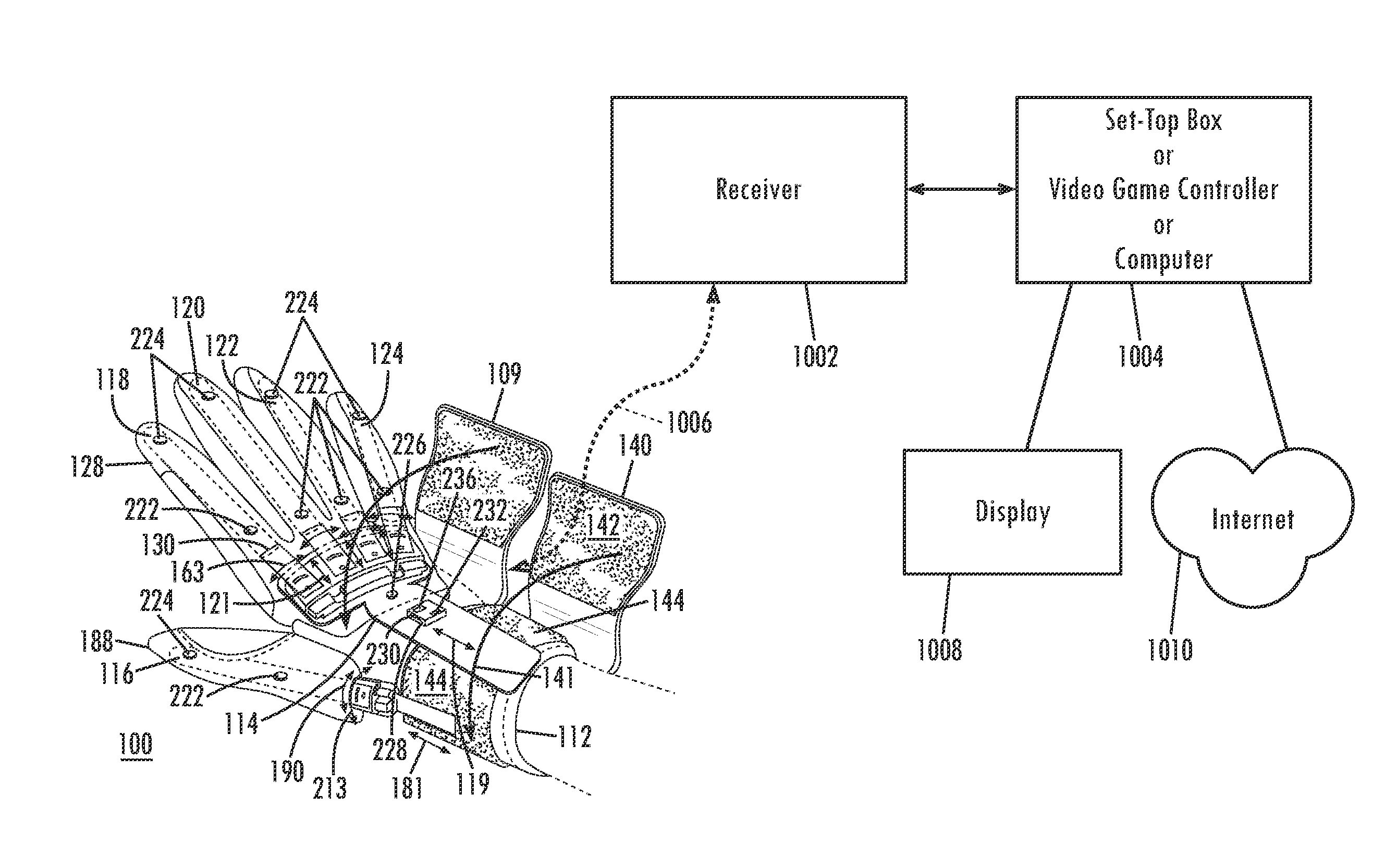
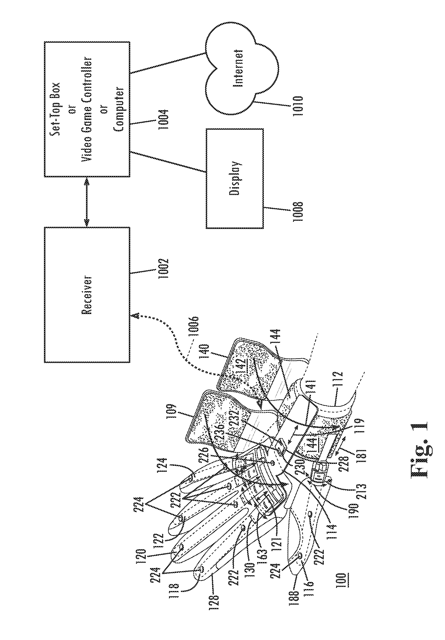
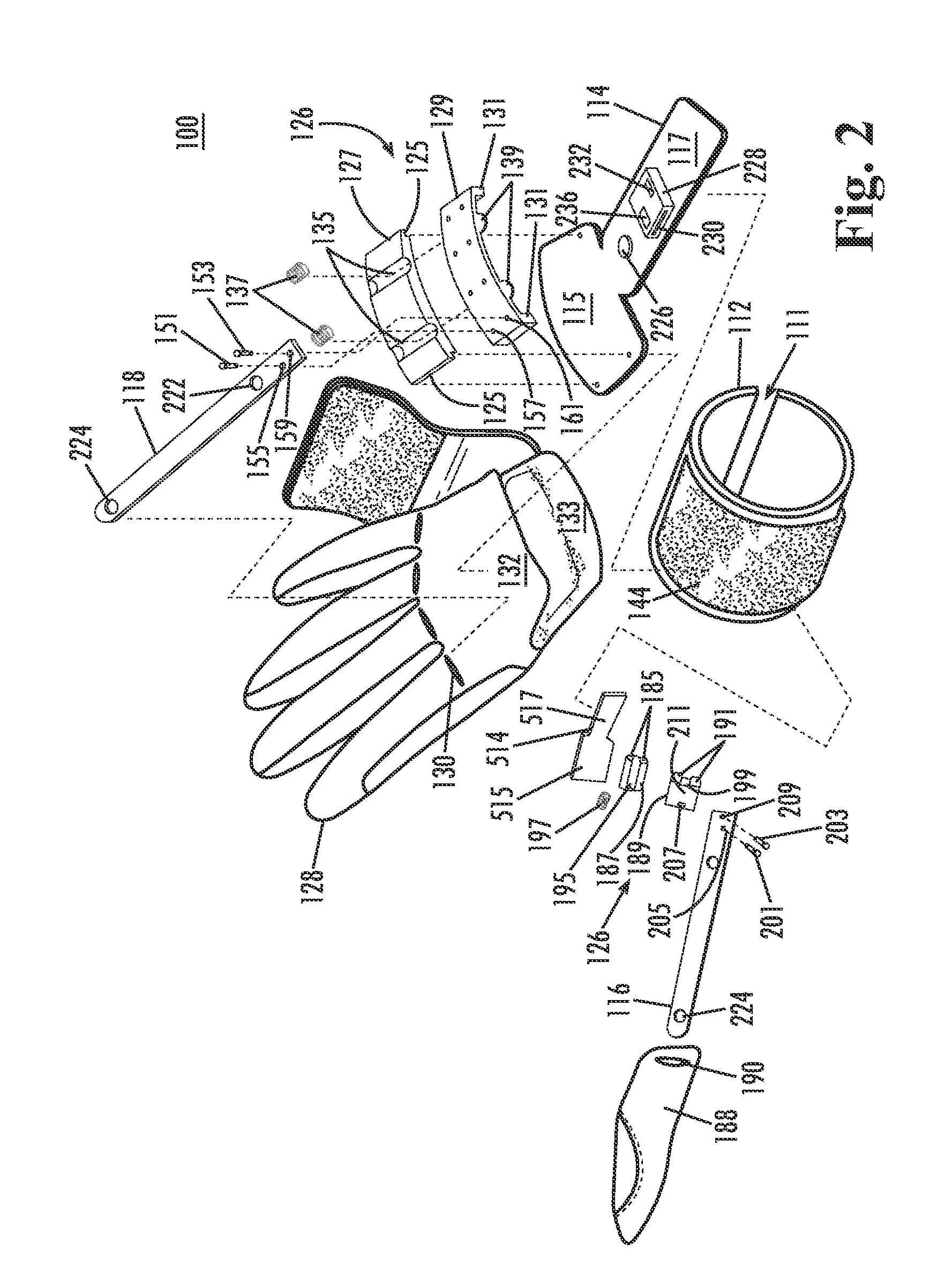
[0036]Referring to FIGS. 1 and 2, a neurological device 100 is shown having a forearm support section 112 and a hand support section 114 that are coupled together as described below. Forearm support section 112 is preferably formed from a flexible material such as plastic, metal, or alloy material. Forearm support section 112 also is configured and dimensioned to extend along a forearm of the user from the wrist rearwardly for a distance of at least several inches, and is generally tubular and designed to surround a portion of the wrist and forearm. Forearm support ...


PUM


Abstract

A neurological device having a forearm support releasably attached to a user's arm, at least one finger sleeve adapted to be releasably attached to at least one finger, at least one tensor strut having a first end releasably coupled to the at least one finger sleeve and an opposite second end coupled to the forearm support, at least one sensor coupled to at least one of the at least one finger sleeve and the at least tensor strut and configured to detect finger movement and generate electrical signals that are indicative of the movement, and a data device coupled to the sensor and configured to receive the electrical signals and calculate at least one of a range of motion of the at least one finger, a speed of movement of the at least one finger, number of repetitions between flexion and extension of the at least one finger and a pressure exerted by the at least one finger during flexion from the electrical signals. The calculated data is used to remotely track user compliance and rehabilitation compliance by a healthcare provider.

Description

CLAIM OF PRIORITY[0001]The present application claims priority to U.S. Provisional Patent Application Ser. No. 61 / 144,952, filed Jan. 15, 2009, entitled Neurological Device, the entire disclosure of which is incorporated by reference herein.FIELD OF THE INVENTION[0002]The present invention relates to the field of neurological rehabilitation device constructions in general, and more particularly to an electronic enabled neurological rehabilitation device for collecting data and interacting with a computer program.BACKGROUND OF THE INVENTION[0003]A dynamic wrist-hand-finger orthosis or splint is generally used for the positioning of an impaired, injured, or disabled wrist, hand, and fingers. Splints come in a variety of designs: static, static progressive, and dynamic that can be low profile or high profile. Most prior art splints are neurological in nature that either holds the hand in a static functional position, or uses a slight dynamic force to position the fingers. None of the k...

Claims


Application Information

Patent Timeline
IPC IPC(8): A63B21/00A61F5/00
CPCA61B5/1125A61B5/4528A61B5/6806A61B5/6825G06F3/014A61B5/6838A61B5/7475A61F5/013A61B5/6826
Inventor HOFFMAN, HENRY B.KLETT, CHRISTOPHER L.KOVACEVICH, IAN D.
Owner SAEBO
Learn More