
Optical metapolarizer device

a technology of optical metapolarizer and polarizer, which is applied in the field of optical metapolarizer devices, can solve the problems of limiting the manufacturability of the device, affecting the polarization effect of light,

Inactive Publication Date: 2010-09-16
RAVENBRICK
View PDF110 Cites 66 Cited by
  • Summary
  • Abstract
  • Description
  • Claims
  • Application Information

AI Technical Summary

Benefits of technology

[0023]This technology has particular, but not exclusive, application as a replacement for traditional polarizers in video displays, liquid crystal optical shutters, and thermoabsorptive or thermoreflective optical attenuators (e.g., window films with temperature-dependent reflectivity and / or absorptivity). Implementations of this technology may be made in non-chiral forms to avoid introduction of ellipticity to the polarized light and therefore avoid inhibition in the contrast ratio of devices such as twisted nematic liquid crystal displays.

Problems solved by technology

Typically these are linear rather than circular polarizers, as high contrast ratio and broad viewing angles may be more difficult to achieve using circular polarizers.
However, even very efficient Faraday rotator materials such as terbium gallium garnet require strong magnetic fields and long optical paths in order to achieve meaningful rotation, making them impractical for most applications.
Both are chiral and therefore non-axisymmetric, which limits their manufacturability.
In addition, because they are chiral these structures act on circularly rather than linearly polarized light, which limits their potential utility in devices such as video displays and optical limiters for the reasons described above, i.e., because high contrast ratio and broad viewing angle are more difficult to achieve using circularly polarized light.
Thus, the use of traditional polarizers places severe limitations on the brightness, energy efficiency, and total light flux of polarizing devices.
When used in video displays and optical filters, such polarizers may result in very low contrast ratios and may therefore be considered undesirable.
Nevertheless, many commercially available polarizers may be significantly less than 100% efficient.
In addition, many polarizers exhibit significant rejection of photons of matched polarity, which may result in lower total transmission even when the polarization efficiency is high.
However, unlike a traditional polarizer, the metapolarizer may not absorb or reflect a large percentage of the incident light in order to achieve this.

Method used


Image

  • Optical metapolarizer device
  • Optical metapolarizer device
  • Optical metapolarizer device

Examples


Embodiment Construction

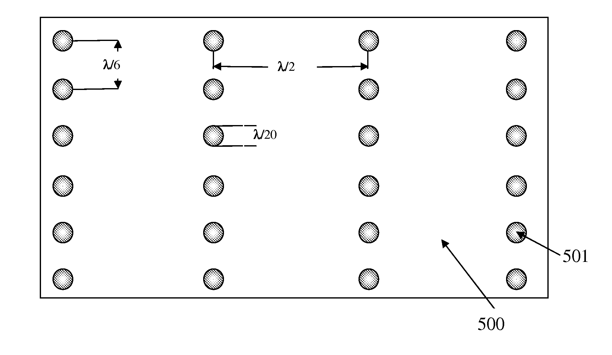
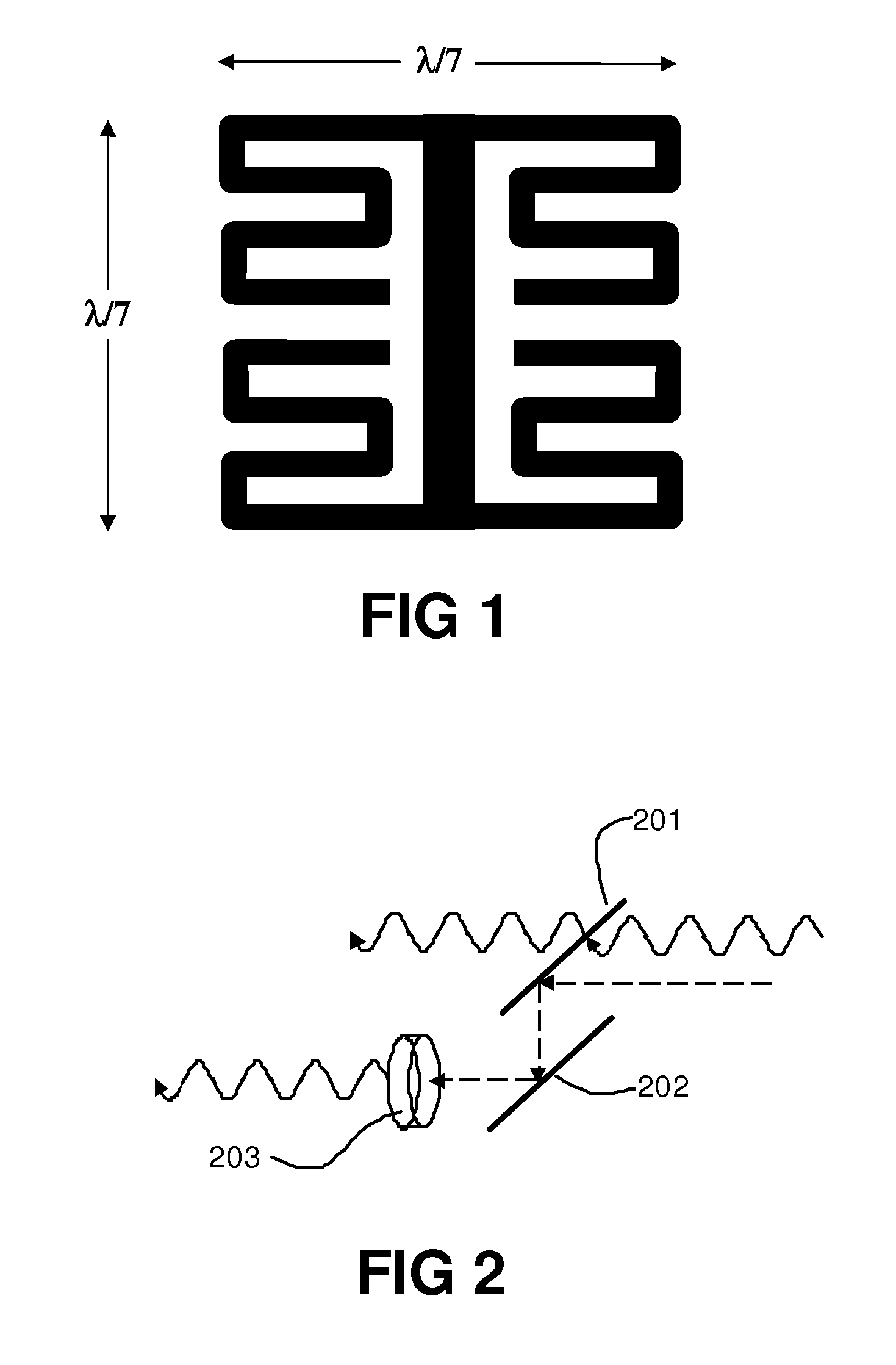
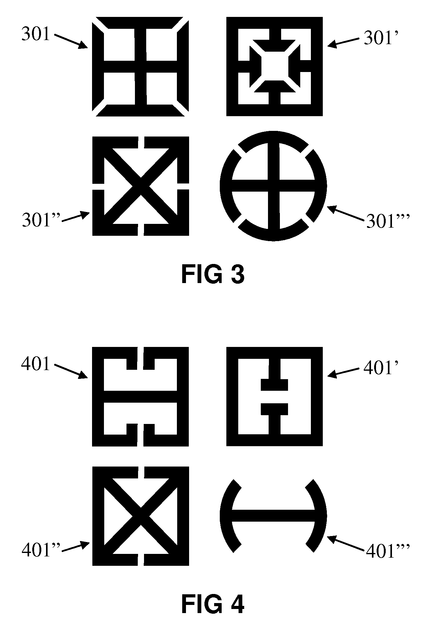
[0052]Metamaterials as disclosed herein with effective permittivity and permeability (∈eff and μeff) in either a double-positive (DPS), single-negative (SNG), or double-negative (DNG) state, may be employed in such a way that the permittivity and permeability may differ for different polarities of light. For example, for one linear polarity of incident light, ∈eff and μeff may be such that the metamaterial is largely transmissive, with minimal reflection, absorption, or phase shifting. For the perpendicular polarity of incident light, ∈eff and μeff may be such that the metamaterial remains largely transmissive with minimal reflection and absorption, but with a substantial phase-shifting effect that alters the relative phase of electric and magnetic fields of a photon, such that the polarity of the photon may be rotated. Thus, the metamaterial device may act as a metapolarizer, i.e., the light exiting the device may be entirely or largely composed of a single polarity, but of an inte...


PUM


Abstract

An optical metapolarizer device polarizes light while mitigating the absorptive or reflective losses associated with traditional polarizers. The metapolarizer device transmits light of one polarity and rotates the other polarity so that it is closer to the transmitted polarity. As a result, although the light exiting the metapolarizer device is highly polarized, the total transmissivity of the device can be well in excess of 50%, and can approach 100% in the theoretical limit.

Description

CROSS REFERENCE TO RELATED APPLICATIONS[0001]This application is related to U.S. provisional patent application Nos. 61 / 074,095 entitled “Optical metapolarizer device” filed 19 Jun. 2008 and 61 / 146,298 entitled “Optical metapolarizer device” filed 21 Jan. 2009, the disclosures of which are hereby incorporated herein by reference in their entireties.STATEMENT REGARDING FEDERALLY SPONSORED RESEARCH OR DEVELOPMENT[0002]This technology was developed with sponsorship by the Defense Advanced Research Projects Agency Grant No. W31P4Q-08-C-0293 and the U.S. federal government has certain rights to this technology.BACKGROUND[0003]1. Field of Technology[0004]This technology relates to the polarization of light with less attenuation than normally associated with absorptive or reflective polarizers.[0005]2. Description of the Related Art[0006]The vast majority of liquid crystal devices in use around the world use absorptive polarizers, which attenuate slightly more than 50% of the light passing...

Claims


Application Information

Patent Timeline
Patent Type & Authority Applications(United States)
IPC IPC(8): G02B27/28
CPCB82Y20/00H01Q15/0086G02B5/3058G02B1/007
Inventor MCCARTHY, WILPOWERS, RICHARD M.PARK, WOUNJHANG
Owner RAVENBRICK
Learn More