
UWB coexistence scheme

Active Publication Date: 2010-09-09
QUALCOMM TECH INT
View PDF2 Cites 17 Cited by
  • Summary
  • Abstract
  • Description
  • Claims
  • Application Information

AI Technical Summary

Benefits of technology

[0028]The above summary of the invention is provided in order to provide a basic understanding of some aspects of the invention. This summary is not intended to identify key or critical elements of the invention or to delineate the scope of the invent

Problems solved by technology

Some combinations of IEEE 802.11a / j and Ultra-Wideband channels, even those that only partially overlap in frequency bandwidth, resulting in mutual interference between the two protocols.
However, these coexistence schemes were designed to operate with Bluetooth and cannot simply be used with a UWB radio to allow UWB and IEEE 802.11 to coexist as the nature of UWB transmission and reception is different to that of Bluetooth.
The closer the channels are, the greater the interference and the stronger one signal is, the more the other signal will suffer from interference.
Current UWB devices are Band Group 1, but future UWB devices used as higher-speed radios for Bluetooth will use frequencies above 6 GHz, due to concerns from cellular phone companies that UWB would interfere with WiMAX or other cellular radios.
Due to both regulatory constraints and those from other organisations (such as the WiMedia Alliance and the Bluetooth SIG), any particular selection of intercommunicating UWB radios are unlikely to have any choice regarding the Band Group that they respectively use.
There will usually be a choice of Band Group for new connections, although it will often be limited.
The PCA approach allows any device to content for access to the medium (in a similar manner to IEEE 802.11) whenever it has not been reserved, but this is less efficient (the radios have to remain active) and this mode is not used by systems such as Wireless USB.

Method used


Image

  • UWB coexistence scheme
  • UWB coexistence scheme
  • UWB coexistence scheme

Examples


Embodiment Construction

[0035]The following description is presented to enable any person skilled in the art to make and use the invention, and is provided in the context of a particular application and its requirements. Various modifications to the disclosed embodiments will be readily apparent to those skilled in the art, and the general principles defined herein may be applied to other embodiments and applications without departing from the spirit and scope of the present invention. Thus, the present invention is not intended to be limited to the embodiments shown, but is to be accorded the widest scope consistent with the principles and features disclosed herein.

[0036]In the UWB protocol, both the beacons and reservations involve both transmit and receive activity, but it is the receive operations that most benefit from protection. The transmit activity can still occur whilst the other protocol is being used to transmit as the transmit signal is strong enough to differentiate itself from the interferen...


PUM


Abstract

Roughly described, a first radio is configured to operate according to a first protocol and configured to use a coexistence signaling scheme with a second radio configured to operate according to a second protocol, wherein the coexistence signaling scheme is configured to allow a radio configured to operate according to the second protocol to be co-located and non-interfering with a radio configured to operate according to a protocol different to the first protocol, and wherein the first radio comprises behavioral logic for generating messages for the second radio in accordance with the coexistence signaling scheme to cause the second radio to adopt behavior suitable for coexistence with the first radio.

Description

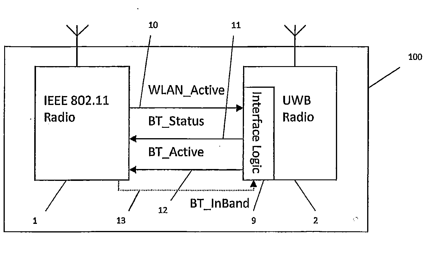
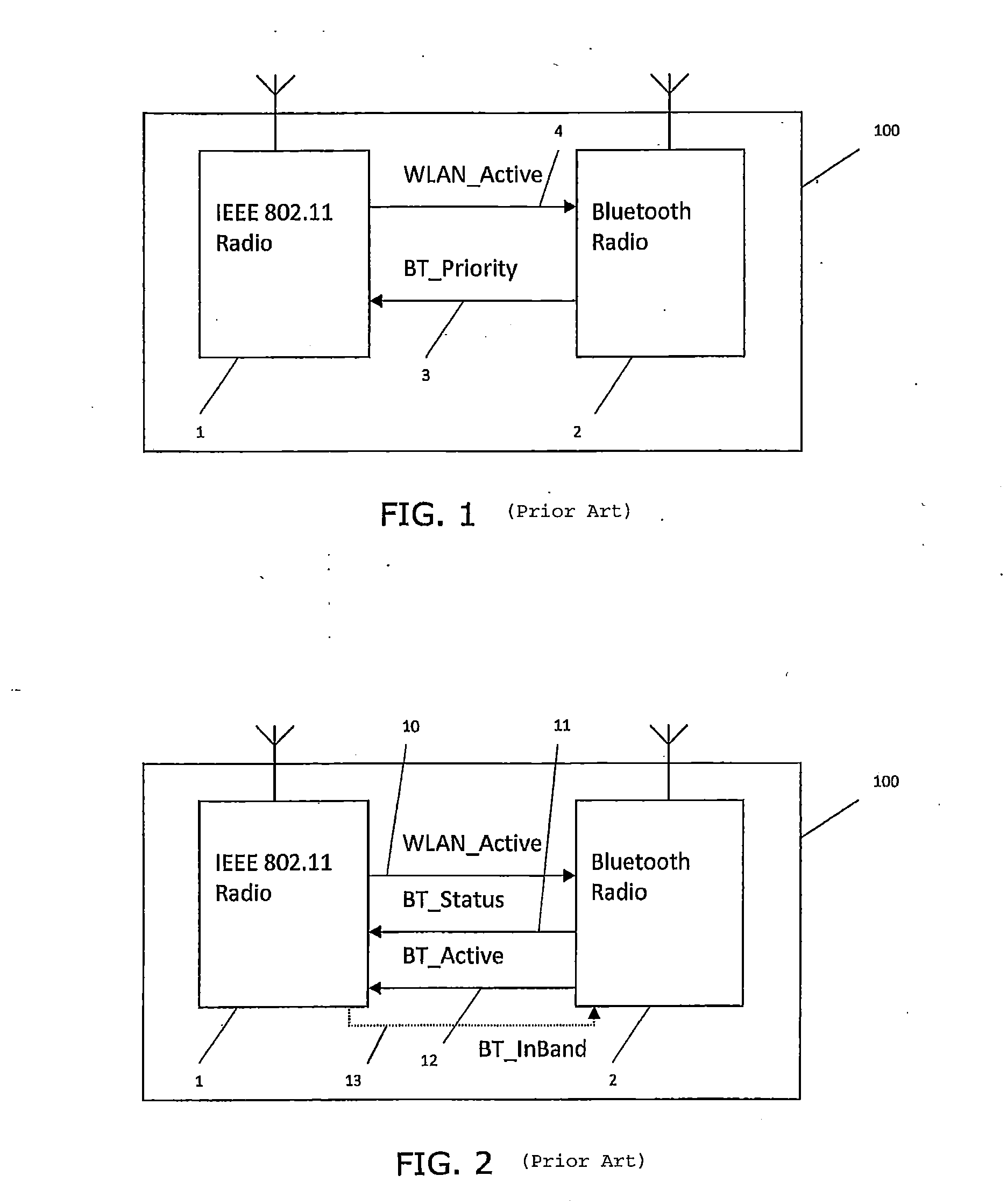
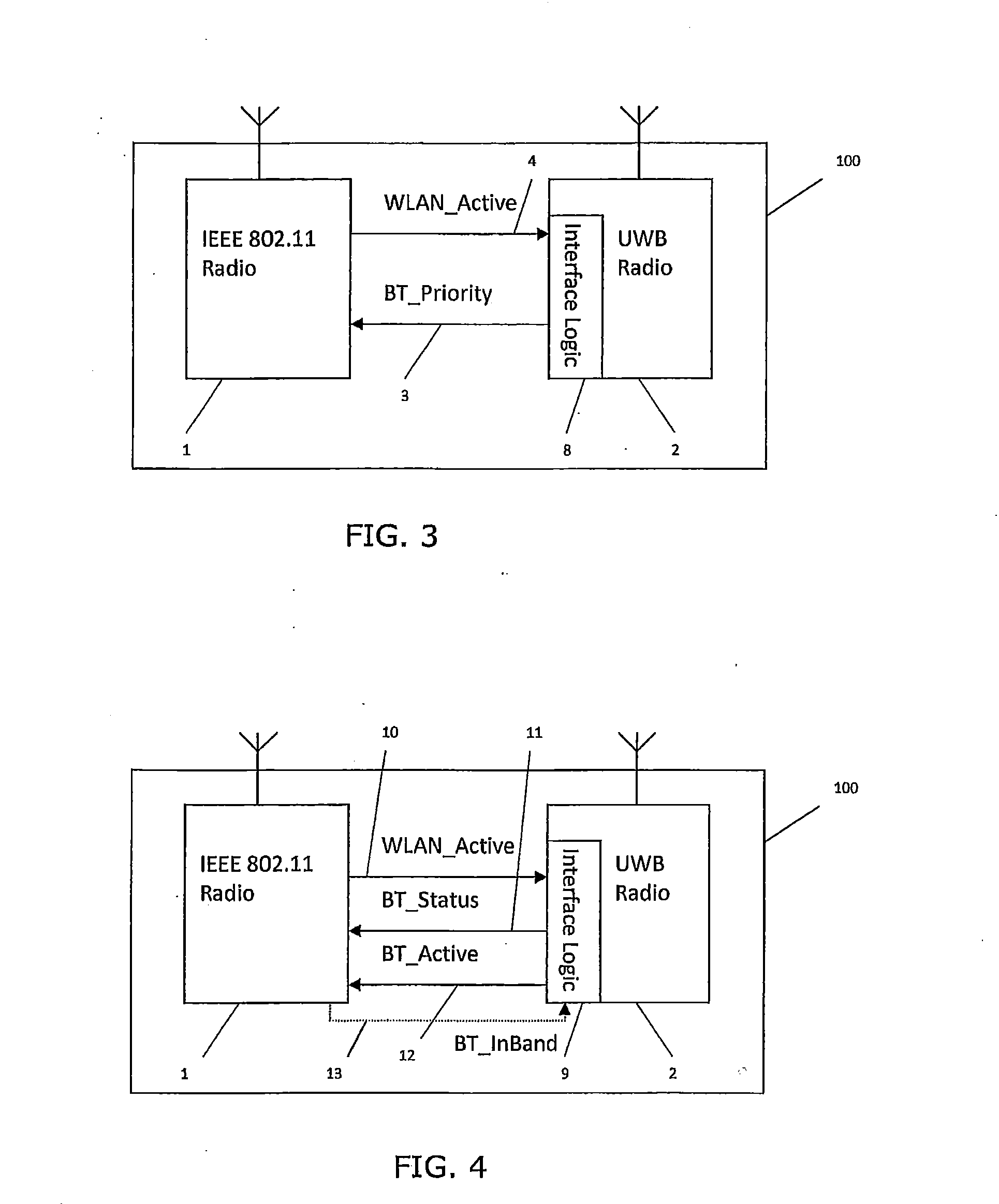
BACKGROUND[0001]This invention relates to communication in environments where interference from signals relating to one communication protocol can hinder the reception of signals relating to another communication protocol.[0002]One example of such an environment is when transceivers for two protocols that occupy the same or adjacent frequency bands are located close to each other or even in the same device: for instance a handheld communication device. As an example, a transceiver for IEEE 802.11a / j wireless LAN (local area network) signals could be located near to or in the same device as a transceiver for Ultra-Wideband (UWB) signals. Some combinations of IEEE 802.11a / j and Ultra-Wideband channels, even those that only partially overlap in frequency bandwidth, resulting in mutual interference between the two protocols. Because of this mutual interference it is desirable to adopt a coexistence scheme that enhances the ability of a receiver for one of those protocols to operate in t...

Claims


Application Information

Patent Timeline
IPC IPC(8): H04W4/00H04B7/005H04B15/00H04W88/06
CPCH04B1/406H04B15/02H04W72/1215H04W88/06H04W16/14
Inventor THOUKYDIDES, ALEXANDER
Owner QUALCOMM TECH INT
Learn More