
Cooling oil circulation of a motor-vehicle transmission with a control valve

a technology of control valve and transmission oil, which is applied in the direction of gearing details, belts/chains/gear parts, gear lubrication/cooling, etc., can solve the problems of increasing the space in this area, not sufficiently dissipating the existing heat of the transmission oil, and increasing the production cost, so as to reduce the space requirements and reduce the manufacturing cost.

Inactive Publication Date: 2010-09-02
ZF FRIEDRICHSHAFEN AG
View PDF8 Cites 10 Cited by
  • Summary
  • Abstract
  • Description
  • Claims
  • Application Information

AI Technical Summary

Benefits of technology

[0008]Therefore, it is the task of this invention to create an oil cooling circulation for a motor vehicle transmission in which placement of a control valve, in the area of the transmission enclosure, can be achieved by lowering space requirements in this area and reducing the manufacturing cost.

Problems solved by technology

However, the surface of the transmission housing is, in the last named case, often not sufficiently dissipate the existing heat of the transmission oil.
It is disadvantageous, in such embodiment of an oil cooling circulation, that an appropriate installation space has to be provided, in the area of the motor vehicle transmission, for the enclosure of the control valve, which has to be connected with pipes, thereby increasing the need for space in this area as well as increasing the production cost.

Method used


Image

  • Cooling oil circulation of a motor-vehicle transmission with a control valve
  • Cooling oil circulation of a motor-vehicle transmission with a control valve
  • Cooling oil circulation of a motor-vehicle transmission with a control valve

Examples


first embodiment

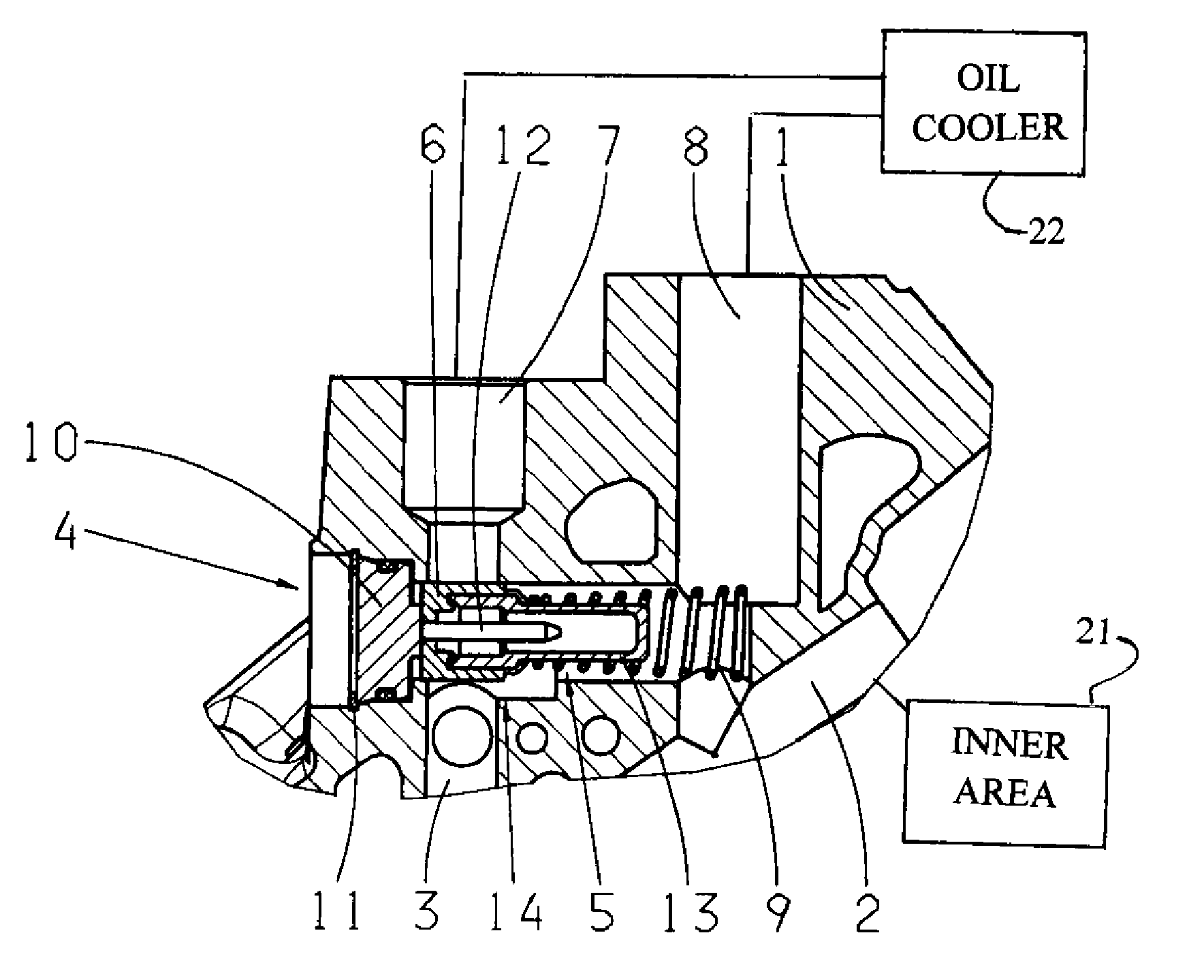
[0027]In FIG. 1, a perspective view of the invented oil cooling circulation can be seen, in accordance with the first embodiment, in the area of a transmission housing 1 in which a input pipeline 2 and a return pipeline 3 are presented, to connect an inner area 21 with an oil cooler 22. A control valve 5 has been placed in the borehole 4 of the transmission enclosure 1, which connects the input pipeline and the output pipeline 2 and 3, according to the position of a valve part 6, with an inlet 7 and an outlet 8 of the oil cooler, to control the amount of transmission oil supplied into the oil cooler. By a return spring 9, this valve part 6 is preloaded against a support part 10, which is secured in the borehole 4 by a snap ring 11 and has, on its side facing the return pipeline 3, a pin-shaped top part in form of a thermostatic work part 12. Depending on its temperature, this thermostatic work part 12 changes its length and hereby initiates the related sliding of the valve part 6. T...

second embodiment

[0029]FIG. 2 shows a perspective partial view of the invented oil cooling circulation in accordance with a Different from the presented variation in FIG. 1, the inlet 7′ out the oil cooler is positioned at the front side of the valve part 6 and in the estuary of the borehole 4. Hereby, on the other side of the control valve 5 a continuation of the return pipeline 3 is closed by a plug 15. To enable a flow of the transmission oil now into the inlet 7′ of the oil cooler, the support part 10′ is constructed as in FIG. 3. One can recognize that in FIG. 3 the support part 10′ has a circular shaped part 16 with a bar 17, which extends through the centerline of the circular shaped part 16 and hereby defines two openings 18A and 18B. This bar 17 also has, in the axial direction, a bent design and has one receptacle 19, on the centerline of the circular shaped part 16, which is positioned for a contact with the thermostatic work part 12, not shown here.

third embodiment

[0030]FIG. 4 presents a detailed sectional view of the invented oil cooling circulation, in accordance with a third embodiment and presented in the area of the control valve 5. Different from the two previously described embodiments, the circular shaped part 16′ has an axial extension through which the borehole cross section of the return pipeline 3 becomes partially closed and through which an oil stream is reduced, when coupled with the inlet 7′ of the oil cooler.


PUM


Abstract

An oil cooling circulation for a vehicle transmission comprising a transmission enclosure (1) having an input pipeline (2) and a return pipeline (3) for oil exchange between the inner area of the transmission and an oil cooler. A control valve (5) is provided which, by activation of a pre-loaded valve part (6) sliding along a center line of the control valve (5), the return pipeline (3) can be coupled with the supply input line (2). The valve part (6) has, at the return pipeline (3), a pin shaped top part and the transmission enclosure (1) has a borehole (4), penetrating the supply input line (2) and the return pipeline (3), in which the control valve (5) is positioned. The valve part (6) of the control valve (5) is slidingly positioned between a borehole bottom and a provided supporting part (10; 10′; 10″; 10′″) in the estuary of the borehole (4).

Description

[0001]This application claims priority from German patent application serial no. 10 2009 001 264.8 filed Mar. 2, 2009.FIELD OF THE INVENTION[0002]The invention relates to an oil cooling circulation in a motor vehicle transmission, in particular an automatic transmission, comprising a transmission enclosure having an input pipeline and a return pipeline for the exchange of oil between an inner area and an oil cooler, positioned outside of the transmission enclosure whereby, between the oil cooler and the inner area, a control valve is provided in which, by activation of a sliding valve part along the longitudinal centerline of the control valve and preloaded by a return spring, the return pipeline can be coupled with the input pipeline whereby the valve part, at the part of the return pipeline, has a pin shaped top part.BACKGROUND OF THE INVENTION[0003]Usually, transmission oil is applied in motor vehicle transmissions to influence, among other things, the frictional value pattern of...

Claims


Application Information

Patent Timeline
Patent Type & Authority Applications(United States)
IPC IPC(8): F16H57/04
CPCY10T74/2189F16H57/0413
Inventor LEICHSENRING, HORSTLANGWALD, OLAF
Owner ZF FRIEDRICHSHAFEN AG
Learn More