
Energy load management method and system

Inactive Publication Date: 2010-08-26
IBM CORP
View PDF6 Cites 19 Cited by
  • Summary
  • Abstract
  • Description
  • Claims
  • Application Information

AI Technical Summary

Benefits of technology

[0023]The present invention advantageously provides a simple method and associated system capable of monitoring and modifying power systems.

Problems solved by technology

Monitoring and modifying power systems typically comprises an inaccurate process with little flexibility.

Method used


Image

  • Energy load management method and system
  • Energy load management method and system
  • Energy load management method and system

Examples


Embodiment Construction

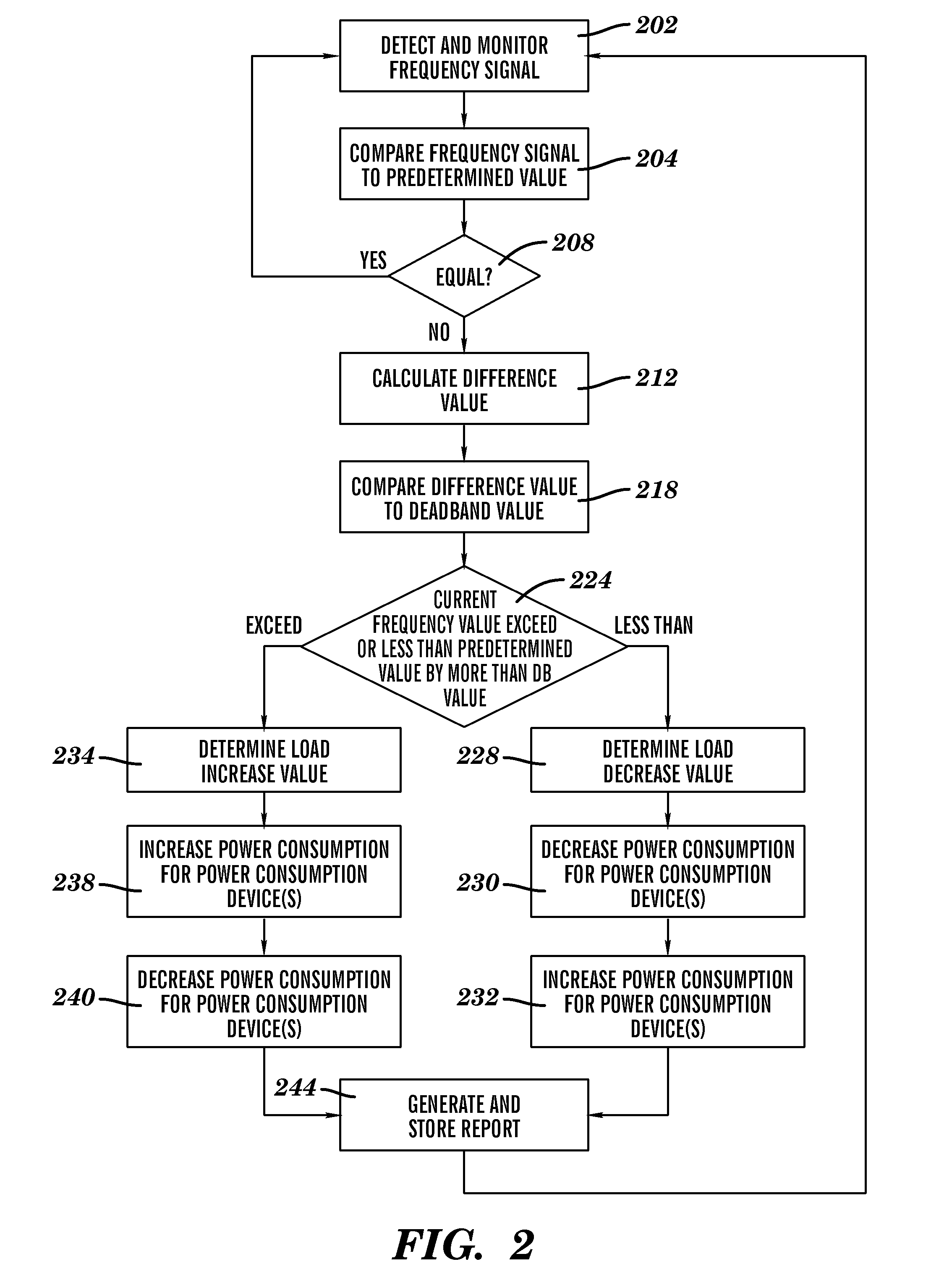
[0027]FIG. 1 illustrates a system 2 for monitoring a frequency signal associated with a supply voltage retrieved from a power grid and performing a load adjustment modification process based on a value of the frequency signal, in accordance with embodiments of the present invention. Load fluctuations associated with power usage by electrical devices (e.g., appliances such as a furnace turning on or off) may cause the frequency signal (e.g., 60 Hertz (Hz)) associated with a supply voltage retrieved from a power grid (e.g., power transmission grid 7) to fluctuate (e.g., rise or fall). Therefore, system 2 is enabled to monitor the frequency signal and perform a load adjustment modification process (e.g., automatically increasing or decreasing a thermostat setting for a furnace) based on a monitored value of the frequency signal.

[0028]System 2 comprises a computing system 8 connected to a utility(s) 5 through a power transmission grid 7. Computing system 8 is additionally connected to e...


PUM


Abstract

A modification method and system. The method includes detecting and monitoring by a computing system, a frequency signal associated with an input voltage signal used for powering a plurality of power consumption devices at a specified location. The computing system compares the frequency signal to a predetermined frequency value. The computing system determines that the frequency signal comprises a first value that is not equal to the predetermined frequency value. The computing system calculates a difference value between the first value and the predetermined frequency value. The computing system compares the difference value to a second value. The computing system enables a load adjustment modification process associated with the plurality of power consumption devices. The computing system generates and stores a report associated with the load adjustment modification process.

Description

FIELD OF THE INVENTION[0001]The present invention relates to a method and associated system for monitoring a frequency signal and performing a load adjustment modification process based on a value of the frequency signal.BACKGROUND OF THE INVENTION[0002]Monitoring and modifying power systems typically comprises an inaccurate process with little flexibility. Accordingly, there exists a need in the art to overcome at least some of the deficiencies and limitations described herein above.SUMMARY OF THE INVENTION[0003]The present invention provides a modification method comprising:[0004]detecting, by a computing system, a frequency signal associated with an input voltage signal used for powering a plurality of power consumption devices at a specified location;[0005]monitoring, by said computing system, said frequency signal;[0006]first comparing, by said computing system, said frequency signal to a predetermined frequency value;[0007]determining, by said computing system based on said fi...

Claims


Application Information

Patent Timeline
IPC IPC(8): G06F1/28
CPCG06Q50/06
Inventor BOSS, GREGORY JENSENHAMILTON, II, RICK ALLENHAUGH, JULIANNE FRANCESSAND, ANNE R.
Owner IBM CORP
Learn More