[0008]The invention is based on the consideration that a contact of the electric conductors or heating wires and a resulting
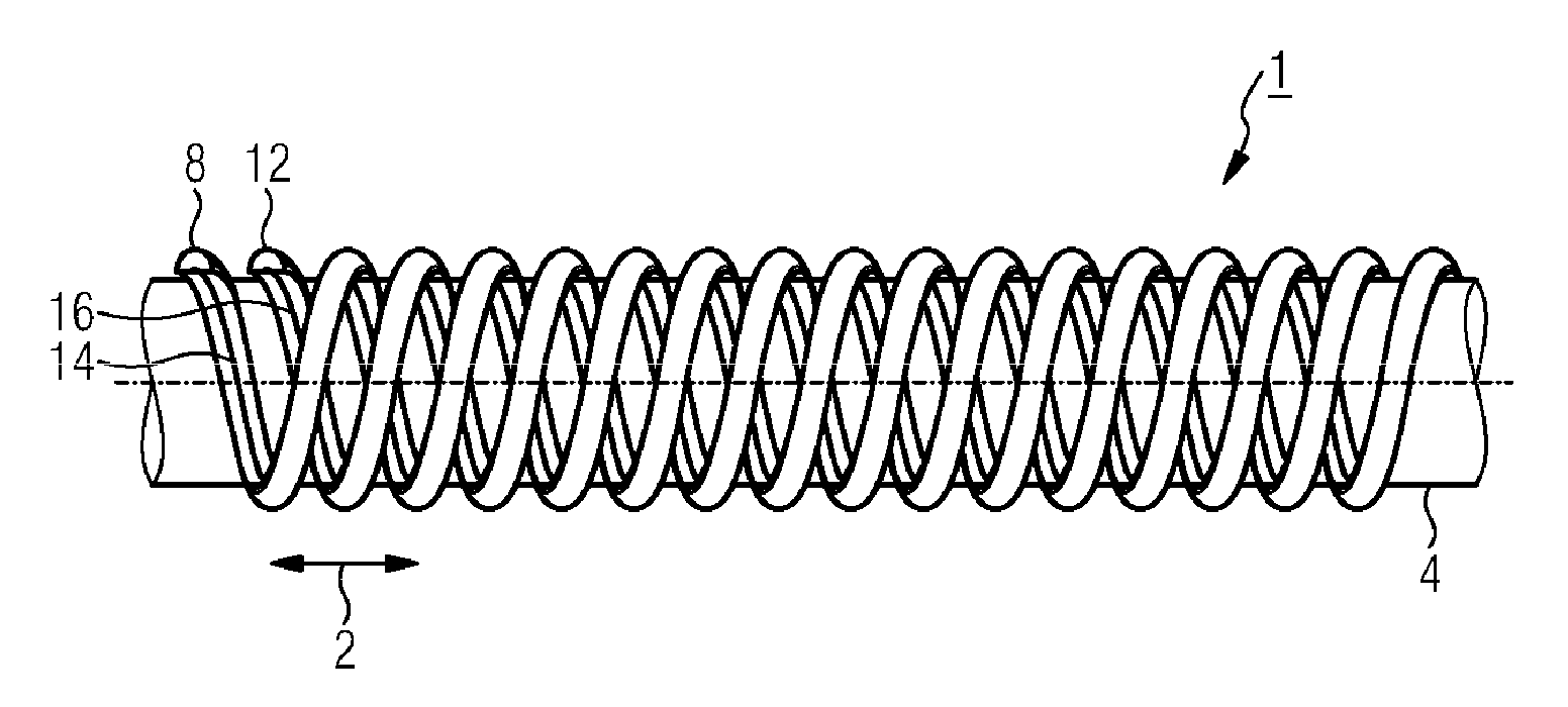
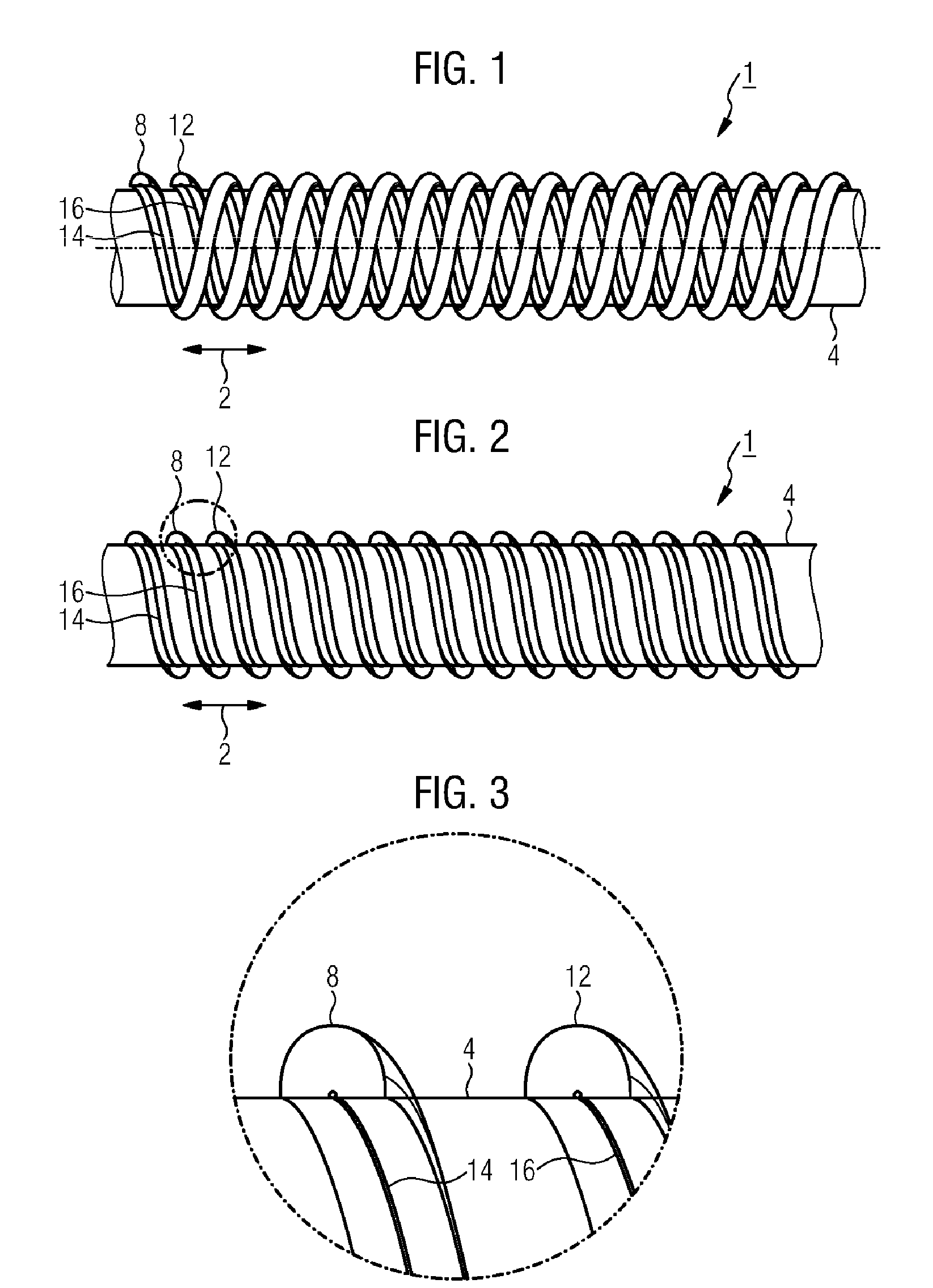
short circuit can consistently be avoided if the heating wires are both electrically insulated and spatially separated from each other. Such an insulation and spatial separation of the heating wires can be achieved by the fact that the hose is helicoidally enclosed by two reinforcing ribs, each helicoidal reinforcing rib accommodating only one single-conductor heating wire.
[0010]On the other hand, such a construction should not impair the flexibility of the hose. It has been found out that this can be achieved by manufacturing the respective spiral with a higher lead than those usual up to now. That means that, as compared with a conventional hose with only one reinforcing spiral, the two reinforcing ribs can be manufactured with higher leads, with identical flexibility of the hose. Viewed in longitudinal direction of the hose, the length of one thread of one of the two reinforcing spirals or reinforcing ribs can be, for example, for a hose according to the invention, twice as long as in the conventional embodiment with only one reinforcing spiral. This reduces the length of the heating wires embedded in the reinforcing spirals, so that material can be saved. Nevertheless, the two spatially separated heating wires guarantee a uniform heating of the hose on all sides.
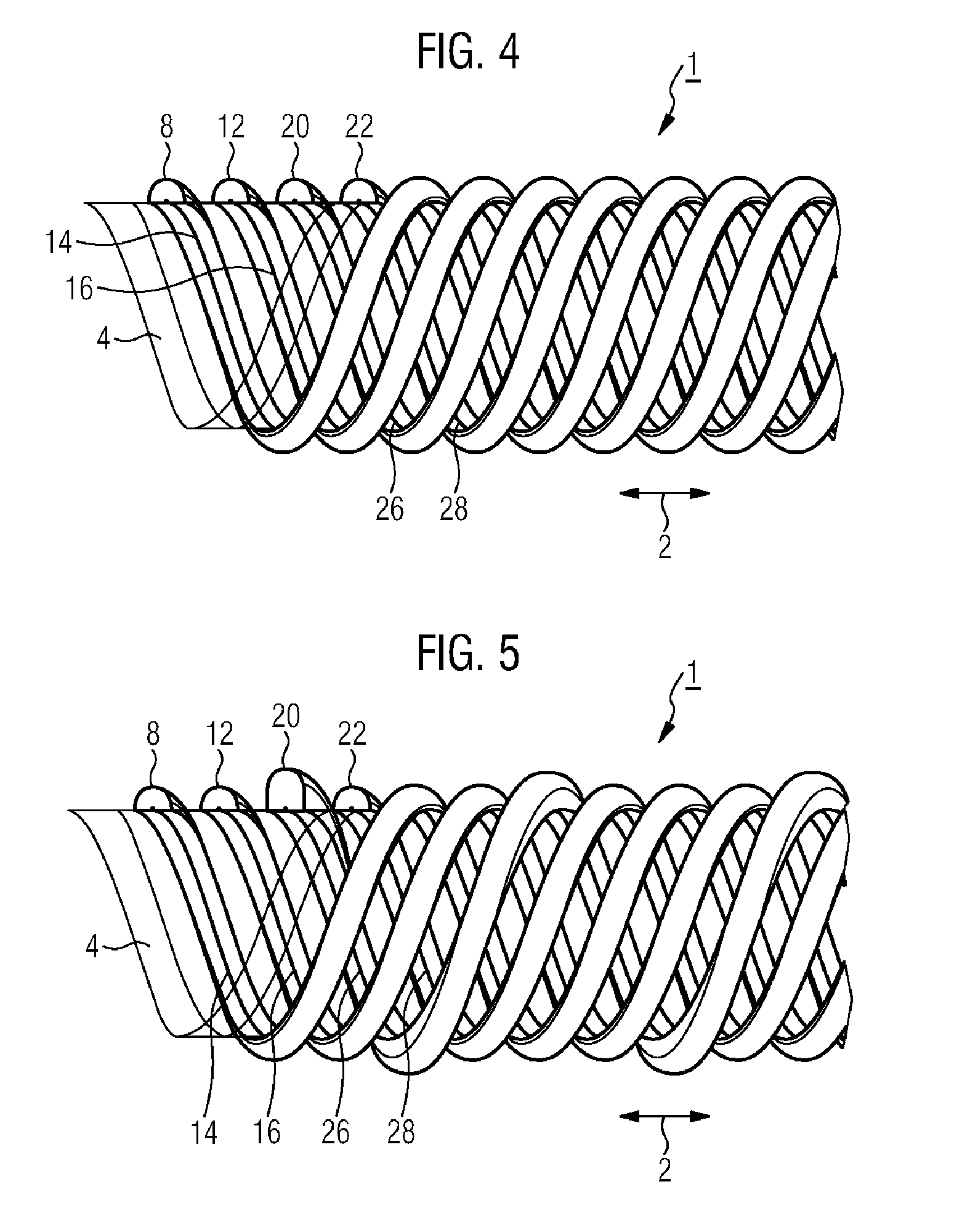
[0013]The use of more than one helicoidal reinforcing rib allows further application-specific realization possibilities of the hose. This can be achieved in particular by making the individual reinforcing ribs of different materials, preferably of different
synthetic materials. In this way, different mechanical properties of the hose can be realized. By using a material of high
Shore hardness for one or more of the reinforcing spirals, for example, the radial strength of the hose can be increased. Furthermore, the abrasion behavior and / or the coefficients of friction can be influenced in an optimized manner through the selection of the materials for the individual reinforcing ribs. The materials may differ in
hardness, abrasion resistance,
surface smoothness or surface adhesion. In this way, characteristics which are typical of a hose, such as radial strength, minimum
bend radius, abrasion resistance, and sliding behavior can be realized in a manner optimized for the specific application.
[0015]The minimum
bend radius of a hose is defined as the
radius of the smallest drum around which the hose can be laid without the hose cross-section considerably changing its original shape. The
bend radius depends among others on the inner
diameter of the hose, the wall thickness and the materials used. If one or more reinforcing spirals are arranged outside the hose wall, the reinforcing spirals will touch each other, when the hose is strongly bent, in the area of the inner curvature. When bending the hose, the minimum bend
radius of the hose will be reached at the latest when all reinforcing ribs touch each other in the area of the inner curvature. If, however, for example, one reinforcing spiral is designed with a laterally convex cross-section and a second reinforcing spiral, with a laterally concave cross-section, the two profiles can slide into one another inside the inner curvature, when the hose is strongly bent. This reduces the distance between the respective central points of the reinforcing spirals, as compared with an embodiment with two convex profiles, and the minimum bend
radius can in this way be kept very small.
[0016]Furthermore, the cross-sectional profile of a helicoidal reinforcing rib can be designed in such a way that it protrudes, in a direction normal to the hose axis, over the other reinforcing ribs, i.e. in a side view of the hose, protrudes further over the hose wall than the other reinforcing ribs. If a hose designed in such a way lies, for example, on a rough, but substantially flat surface, the hose will have contact with the surface underneath it with this protruding reinforcing spiral only. In this way, the number of contact points of the hose with the surface underneath it can be reduced, thus reducing the risk of a catching of the hose on a surface. Variations of the
geometric design of the reinforcing ribs can influence the properties of the hose not only concerning radial strength and bend radius, but can also provide additional possibilities of fastening end pieces on the hose.
[0020]The advantages achieved with the invention consist in particular in that the use of two helicoidal reinforcing ribs, each of which carrying only one single-conductor heating wire, can reliably avoid a contact of the two conductors and, therefore, a short circuit. If two or more reinforcing spirals are used, winding around the hose wall in the manner of a double or multiple
helix, these can be made with a higher lead than in an embodiment with only one reinforcing spiral. This can, on the one hand, guarantee a high flexibility of the hose and, on the other hand, save material for the heating wires. The use of more than two reinforcing ribs allows to additionally carry control or measuring lines. Different embodiments of the respective reinforcing spirals with regard to their color, cross-section and material properties offer a multitude of parameters, through which the characteristics and handling of the hose for the application in question can be adapted in an optimized manner.


