
Camera adaptor for a medical-optical observation instrument and camera-adaptor combination

a technology of optical observation instrument and camera adaptor, which is applied in the field of camera adaptor and camera adaptor, can solve the problems of unimpeded operation of medical practitioners by the camera adaptor, and achieve the effects of compact design, moderate production cost, and good imaging quality

Active Publication Date: 2010-08-26
CARL ZEISS MEDITEC AG
View PDF15 Cites 11 Cited by
  • Summary
  • Abstract
  • Description
  • Claims
  • Application Information

AI Technical Summary

Benefits of technology

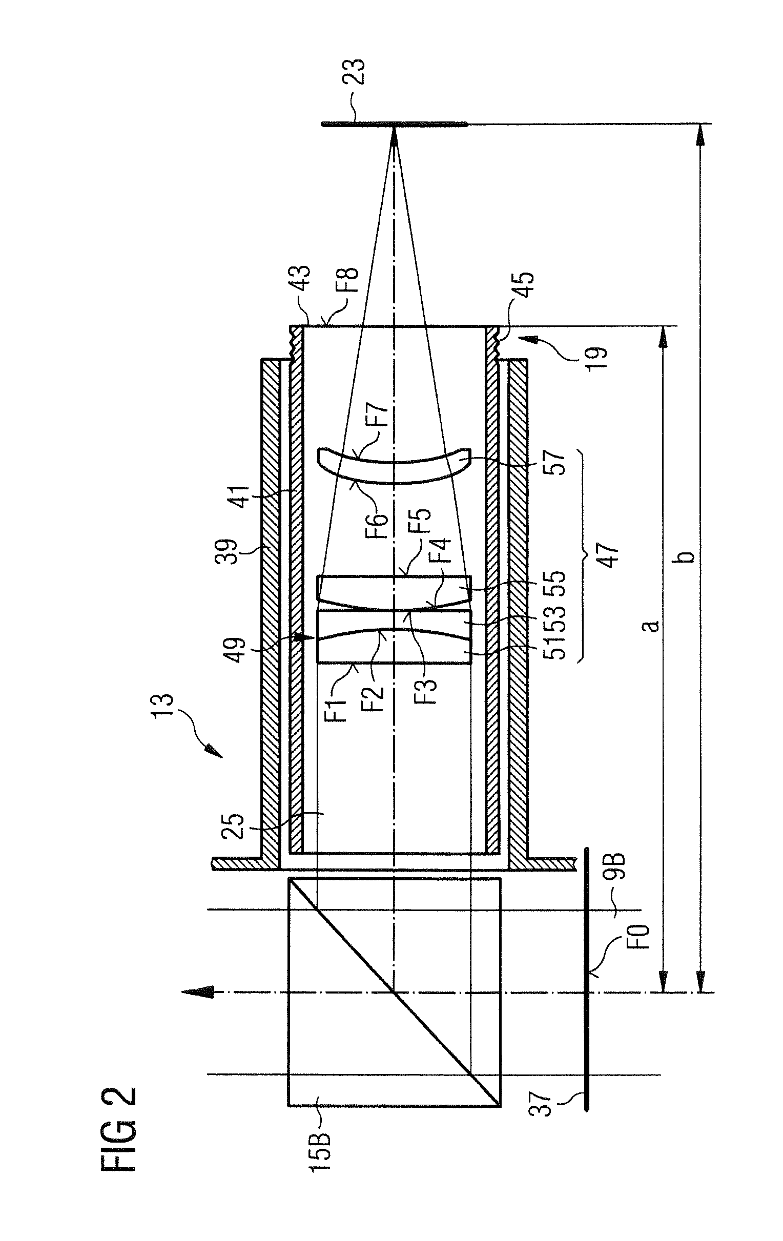
[0011]The objective-lenses combination and the linear optical axis, i.e. the dispensation of an angled optical axis, utilized in the camera adaptor according to the invention afford a reduced installation length of the camera adaptor according to the invention compared to camera adaptors from the prior art. Here, the invention is based, inter alia, on the recognition that the current conventional use of electronic image sensors, for example CCD sensors or CMOS sensors, makes electronic image erection possible in order to obtain a display of the observation object that is the right way up and the right way round, and that therefore deflecting optical elements such as mirrors or prisms can be dispensed with in the adaptor.
[0031]The camera-adaptor combination according to the invention allows the implementation of the advantages of the camera adaptor according to the invention in conjunction with imaging the right way up and the right way round.

Problems solved by technology

As a result of the reduced dimensions of the optical path, the operating medical practitioner reliably remains unimpeded by the camera adaptor, particularly in the case of surgical microscopes.

Method used


Image

  • Camera adaptor for a medical-optical observation instrument and camera-adaptor combination
  • Camera adaptor for a medical-optical observation instrument and camera-adaptor combination
  • Camera adaptor for a medical-optical observation instrument and camera-adaptor combination

Examples


Embodiment Construction

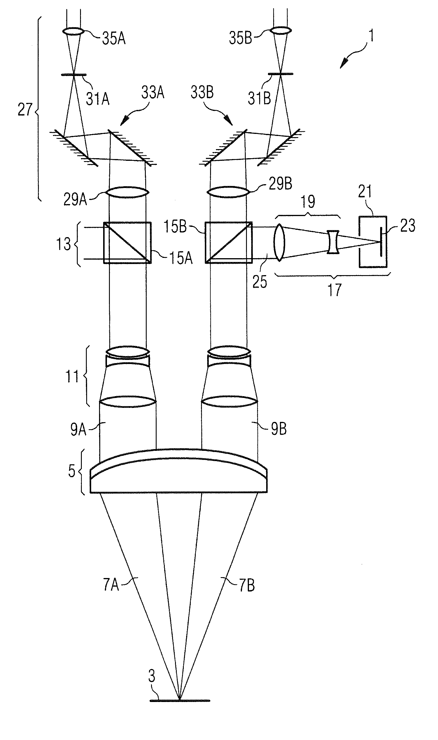
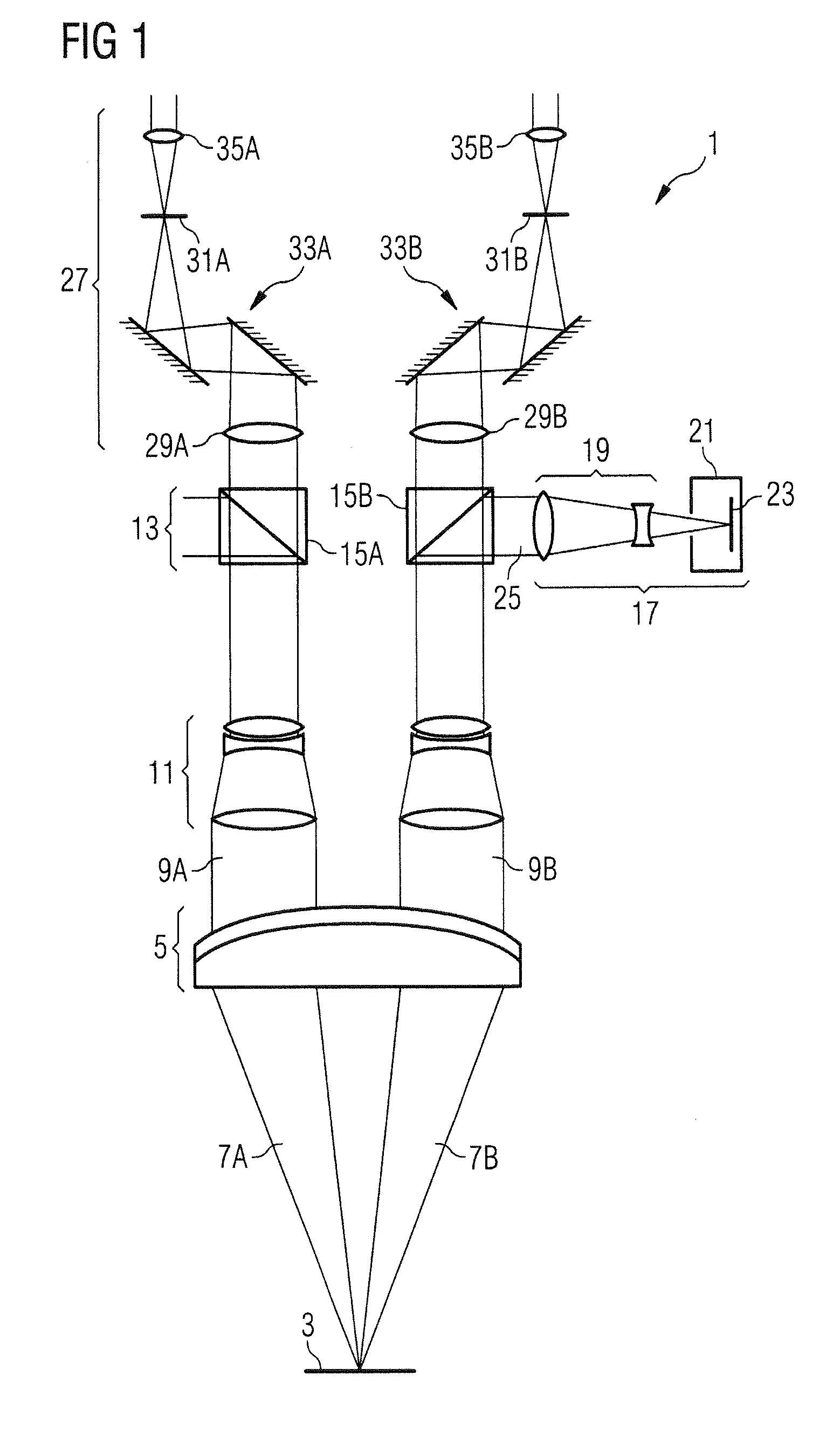
[0047]The basic design of a surgical microscope with a camera-adaptor combination arranged thereon will be explained in the following text with reference to FIG. 1.

[0048]The surgical microscope 1 comprises, as an essential component, an objective 5 to face an observation object 3, which objective is illustrated in the present exemplary embodiment as a cemented component constructed from two partial lenses cemented together. The observation object 3 is arranged in the focal plane of the objective 5 and so a divergent bundle of rays emanating from the observation object 3 is imaged at infinity by the objective 5, that is to say the bundle of rays is converted into a parallel bundle of rays 9 after passing through the objective 5. Instead of a single objective lens, as is used in the present exemplary embodiment, it is however also possible to use an objective-lenses system made of a plurality of single lenses, such as a so-called varifocal lens system, by means of which the working di...


PUM


Abstract

A camera adaptor (19) is provided for connecting a camera (21) to an interface (13) of a medical-optical observation instrument (1) with a parallel beam path. The interface (13) is situated in the parallel beam path (9a, 9b) of the medical-optical observation instrument (1). The camera adaptor (19) has an instrument connector part (41) for connection to the interface (13) of the medical-optical observation instrument (1) and a camera connector part (43, 143) for connection to a camera (21). The beam path (43) runs through the camera adaptor (19) along a linear optical axis. The camera adaptor (19) has an objective-lenses combination (47) with a total focal length between 40 mm and 120 mm. A lens with a positive partial focal length leading on the instrument side in the objective-lenses combination (47) and is followed, on the side toward the camera, by a lens with a negative partial focal length.

Description

BACKGROUND OF THE INVENTION[0001]1. Field of the Invention[0002]The present invention relates to a camera adaptor for a medical-optical observation instrument, in particular for a surgical microscope. In addition, the present invention relates to a combination of a camera adaptor and a camera.[0003]2. Description of the Related Art[0004]So-called phototubes are often available in research microscopes for photographic or video-technical recording of an observation object. In the case of a stereoscopic microscope, there then is, for example, a third connecting piece to which a camera housing without a camera objective is generally connected, in addition to the two eyepiece connecting pieces. However, DE 200 10 121 U1 has also disclosed camera adaptors, which have an attachment apparatus for a camera and allow the use of a camera with an objective on the photo connecting piece. If there is no phototube on the microscope, it is possible to use a camera adaptor as described in US 2001 / 00...

Claims


Application Information

Patent Timeline
IPC IPC(8): G03B17/48G03B41/00
CPCA61B19/5212A61B19/5223G02B21/20G02B23/18G03B17/48G03B41/00G02B21/361G02B21/22A61B90/361A61B90/20
Inventor SCHUTE, STEFANHOGELE, ARTUR
Owner CARL ZEISS MEDITEC AG
Learn More