
GNSS moving base positioning

a technology of moving base and positioning position, which is applied in the field of global navigation satellite system gnss, can solve the problems of significant error in estimated rover position, incurring delay, and inability to run the full weighted-average solution

Active Publication Date: 2010-08-26
TRIMBLE NAVIGATION LTD
View PDF51 Cites 23 Cited by
  • Summary
  • Abstract
  • Description
  • Claims
  • Application Information

AI Technical Summary

Benefits of technology

[0039]In some embodiments, determining a first-epoch rover position relative to a moving base location is repeated at a first rate, and determining a subsequent-epoch update is repeated at a secon...

Problems solved by technology

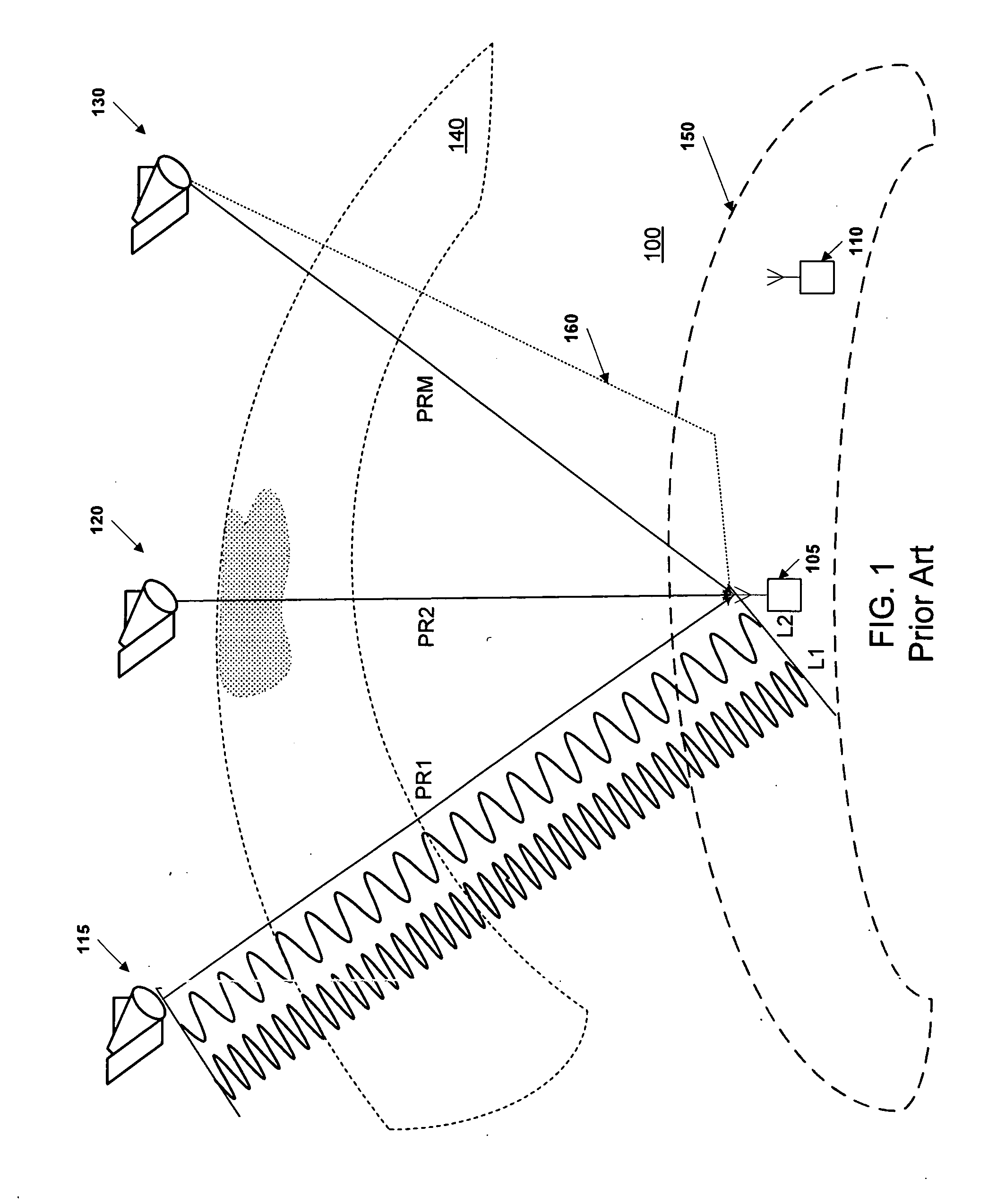
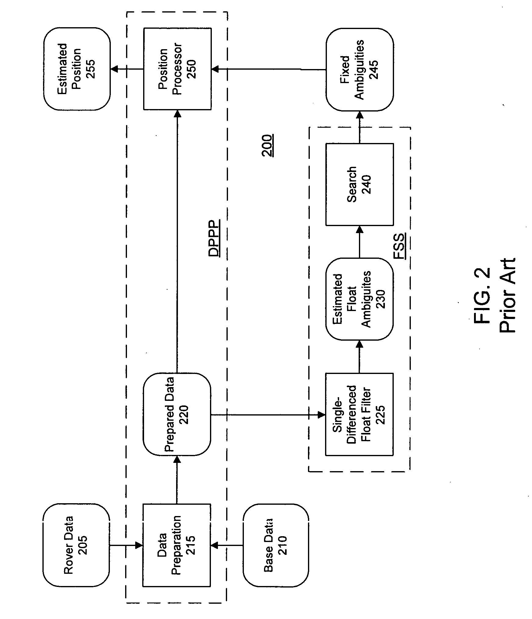
A disadvantage of this approach is that incorrect fixing of the carrier-phase ambiguities can result in a significant error in estimated rover position.
Should this occur, the iterative filters used in the estimation process must be reset, incurring a delay until the ambiguities are again estimated and fixed for use in determining rover position.
A drawback of this approach is that it is not feasible to run the full weighted-average solution at the highest observation-data rate of the receivers in a device having limited computing power, such as in the processor of a mobile rover receiver.
A drawback of this approach is that unmodelled variation in the satellite clocks plus changes in the atmospheric delay cause the undifferenced delta phase position estimates to accumulate errors over time.
The longer the time delta, the larger the error accumulated in the position estimates.

Method used


Image

  • GNSS moving base positioning
  • GNSS moving base positioning
  • GNSS moving base positioning

Examples


Embodiment Construction

Part 1

Moving Base Concepts

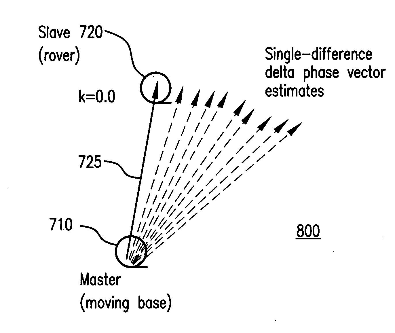
[0059]An important machine control application of RTK GNSS is the precise positioning of the blade cutting edge of graders, bulldozers, excavators and scrapers. For example, the Trimble MS990 system is an integrated GNSS receiver / antenna which can be mounted on masts located at either end of the cutting blade. One of these is considered a “master” (moving base) and the other a “slave” (rover).

[0060]FIG. 6 shows in plan view an example 600 in which a master unit 605 (moving base) is located on the right side of a blade 610 of a bulldozer 615, and a slave unit 620 (rover) is located on the left side of the blade. The master unit 605 uses corrections from a fixed base receiver 625 to perform RTK positioning and thereby to determine the location of the right end of the blade 610 relative to the fixed base 625. The master unit 605 then transmits its RTK position plus GNSS carrier phase data, for example at 10 Hz, to the slave unit 620 mounted on the other end of...


PUM


Abstract

Methods and apparatus are presented for determining a position of an antenna of a GNSS rover from observations of GNSS signals collected at the antenna over multiple epochs and from correction data for at least one of the epochs. A first-epoch rover position relative to a moving base location is determined, a second-epoch update of the first-epoch rover position relative to the moving base location for a second epoch is determined using a single-differenced delta phase process, and the first-epoch position and the second-epoch update are combined to obtain a second-epoch rover position relative to a moving base location of the second epoch.

Description

CROSS REFERENCE TO RELATED APPLICATIONS[0001]The following are related hereto and incorporated herein in their entirety by this reference: U.S. Provisional Application for Patent No. 61 / 208,340 filed 22 Feb. 2009 (TNL A-2347P); International Patent Application PCT / US / 2009 / 004471 filed 5 Aug. 2009 (TNL A-2526PCT); International Patent Application PCT / US / 2009 / 004473 filed 5 Aug. 2009 (TNL A-2525PCT); International Patent Application PCT / US / 2009 / 004474 filed 5 Aug. 2009 (TNL A-2524PCT); International Patent Application PCT / US / 2009 / 004472 filed 5 Aug. 2009 (TNL A-2523PCT); International Patent Application PCT / US / 2009 / 004476 filed 5 Aug. 2009 (TNL A-2339PCT); U.S. Provisional Application for Patent No. 61 / 189,382 filed 19 Aug. 2008 (TNL A-2339P); U.S. patent application Ser. No. 12 / 224,451 filed 26 Aug. 2008, United States Patent Application Publication US 2009 / 0027625 A1 (TNL A-1789US); International Patent Application PCT / US07 / 05874 filed 7 Mar. 2007, International Publication No. WO 2...

Claims


Application Information

Patent Timeline
IPC IPC(8): G01S19/41
CPCG01S19/44
Inventor TALBOT, NICHOLAS CHARLESVOLLATH, ULRICH
Owner TRIMBLE NAVIGATION LTD
Learn More