
Heated tip implant delivery system

a delivery system and tip technology, applied in the field of delivery systems, can solve the problems of device name and logos, non-functional design elements of devices, etc., and achieve the effect of short time span

Inactive Publication Date: 2010-08-19
WARSAW ORTHOPEDIC INC
View PDF8 Cites 28 Cited by
  • Summary
  • Abstract
  • Description
  • Claims
  • Application Information

AI Technical Summary

Benefits of technology

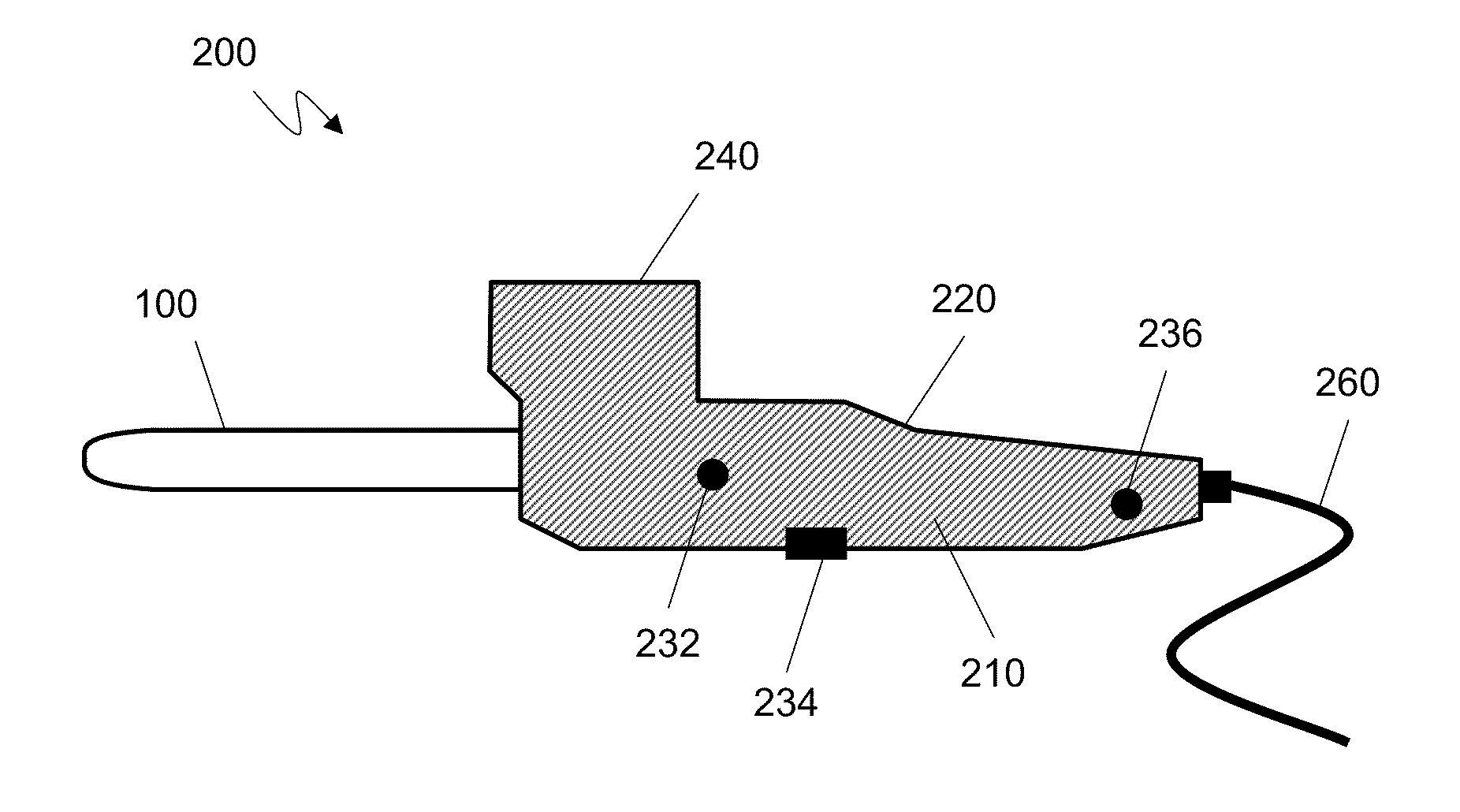
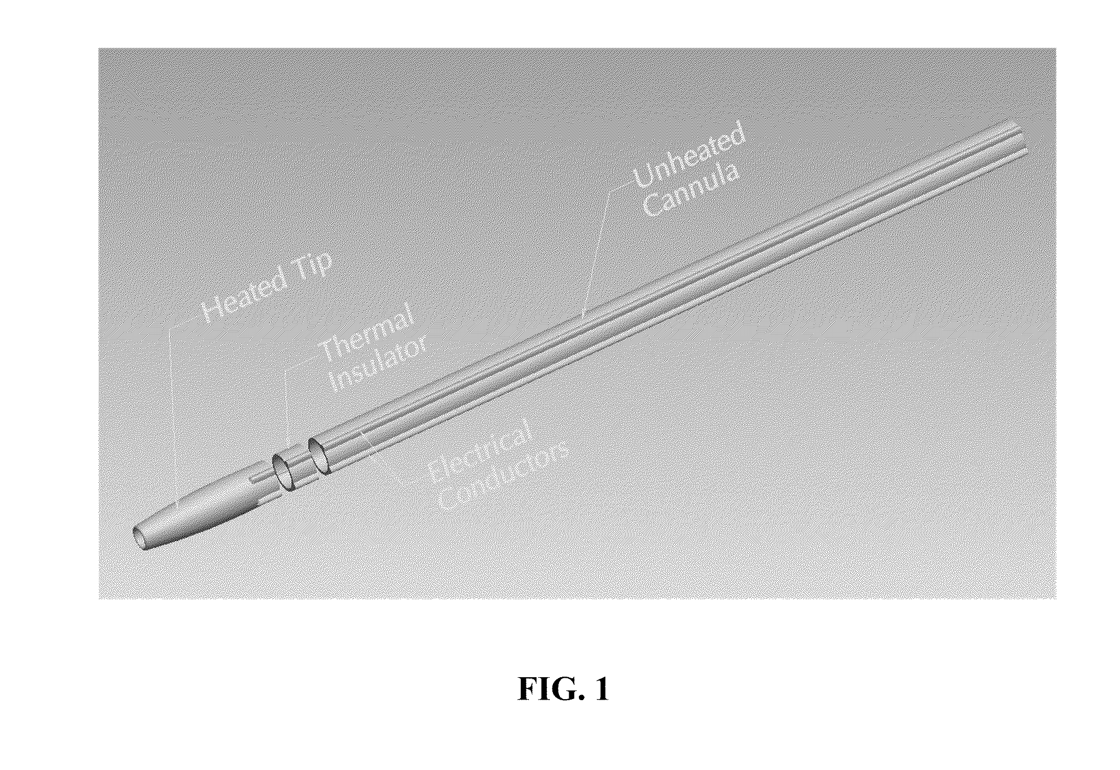
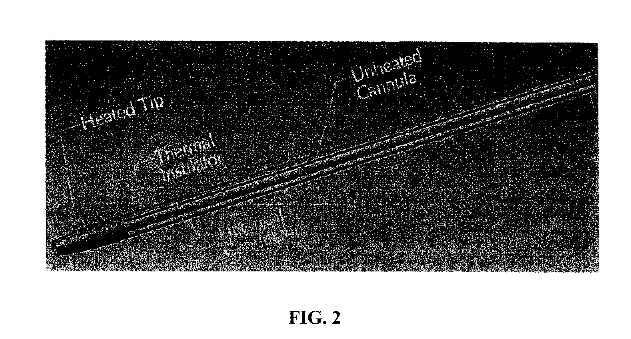
[0010]In another aspect, the invention provides methods of heating a bone substitute material to a temperature ranging from about 45° C. to about 80° C. using an inventive device so that the material becomes flowable and can be delivered through a heated cannula or tip as described herein or a delivery device (e.g., a glue gun-like or cookie press device) as described herein. Exemplary bone substitute materials that can be heated using the inventive methods and devices include composites having a bone, mineral, or ceramic component and a polymer component. Examples of such bone / polymer composites are described in published U.S. patent applications, US 2005 / 0008672, published Jan. 13, 2005; US 2007 / 0191963, published Aug. 16, 2007; and US 2008 / 0069852, published Mar. 20, 2008; each of which is incorporated herein by reference. In certain embodiments, the material is a thermoplastic composite. In certain embodiments, the material is a thermoplastic polymer. The bone substitute material is loaded into an inventive device and heated to a specified temperature as it is advanced through the heated cannula, tip, or other device. The heated material is delivered to an implantation site (e.g., bony defect, joint to be fused, bone segments or fragments to be united, etc.) of a subject using the device. Therefore, heat is applied to the material just as it is being delivered. In certain embodiments, the steps are performed in a sterile environment such as an operating room. The bone substitute materials may be provided packaged sterilely and conveniently for loading into a hot melt delivery device as described herein. The material may be packaged, and the packaging is removed only prior to loading of an inventive device. Given that the bone substitute material is frequently used in a surgical setting, the method preferably provides sterile, flowable material in a short span of time.

Problems solved by technology

Furthermore, the device may include non-functional design elements such as names, logos, lettering, casing, and coloring.

Method used


Image

  • Heated tip implant delivery system
  • Heated tip implant delivery system
  • Heated tip implant delivery system

Examples


Embodiment Construction

[0039]The present invention stems from the recognition that it would be useful to be able to conveniently heat bone substitute materials that become flowable at elevated temperatures in a device that could also be used to administer the heated material. Such a device would heat the material using the heated tip of a cannula or a device similar to a hot melt glue gun. The device would heat the material as it is advanced through the heated cannula or tip; therefore, the material would be heated just as it is being delivered. This would avoid heating the material for an unnecessarily long period of time before administration and therefore prevent the degradation of biological components (e.g., proteins, cells) of the material. The invention also provides methods of using the inventive device to heat bone substitute materials. Kits that include the device and materials for use in the device are also provided by the present invention.

[0040]Bone substitute materials such as bone / polymer c...


PUM


Abstract

Bone substitute materials have been developed that become flowable upon heating. In order to use these new materials in the special environment of an operating room, methods and devices have been developed to conveniently and sterilely heat samples of the material as the material is being implanted into a patient. Inventive heating devices include cannulas with a heated tip and devices similar to a hot melt glue gun. Therefore, the material is heated for only a short time preventing the degradation of biological components of the material.

Description

CROSS REFERENCE TO RELATED APPLICATIONS[0001]The present application is a non-provisional patent application claiming the benefit of and priority to U.S. provisional patent application Ser. No. 61 / 152,392, filed Feb. 13, 2009, the entire disclosure of which is incorporated herein by reference.FIELD OF THE INVENTION[0002]This invention pertains to a delivery system for heating and delivering a bone substitute material, such as a bone / polymer composite that is made flowable upon heating.BACKGROUND OF THE INVENTION[0003]Bone is a composite material composed of impure hydroxyapatite, collagen, and a variety of non-collagenous proteins, as well as embedded and adherent cells. Bone can be processed into an implantable biomaterial, such as an allograft. The processed bone biomaterial can have a variety of properties depending upon the specific processes and treatments applied to it, and it may incorporate characteristics of other biomaterials (e.g., polymers) with which it is combined. For...

Claims


Application Information

Patent Timeline
IPC IPC(8): A61B18/04A61B17/56
CPCA61F2/4601A61B17/8836
Inventor WINTERBOTTOM, JOHN M.KAES, DAVID R.
Owner WARSAW ORTHOPEDIC INC
Learn More