Torque limiter arrangement for a horizontal grinder

a technology of torque limiter and horizontal grinder, which is applied in the direction of gearing elements, clutches, gearing components, etc., can solve the problems of bringing all of the drive components to a stop, affecting the operation of the machine, and causing considerable damage, so as to reduce the size and capacity of the required torque limiter device, improve the torque limiter arrangement, and reduce the cost of the arrangement

Inactive Publication Date: 2010-08-19
BRUNEL GMBH
View PDF15 Cites 8 Cited by
  • Summary
  • Abstract
  • Description
  • Claims
  • Application Information

AI Technical Summary

Benefits of technology

[0007]It is the object of the present invention to improve such a torque limiter arrangement so as to reduce the size and capacity of the required torque limiter device itself to thereby reduce the cost of the arrangement.

Problems solved by technology

Such mills occasionally jam, potentially bringing all of the drive components to a stop.
Such large engines cannot be allowed to stop in this event as considerable damage can be done to the engine components in such an event.
This could possibly create increased damage to the mill components by the momentum of those components being absorbed by the now stopped mill.
The installation of a torque limiter device in the driven sheave requires a large capacity costly device since the driven sheave transmits substantial torque by virtue of the reduction ratio between the sheaves in order to increase the torque applied to the hammer mill.

Method used


Image

  • Torque limiter arrangement for a horizontal grinder
  • Torque limiter arrangement for a horizontal grinder
  • Torque limiter arrangement for a horizontal grinder

Examples


Embodiment Construction

[0015]In the following detailed description, certain specific terminology will be employed for the sake of clarity and a particular embodiment described in accordance with the requirements of 35 USC 112, but it is to be understood that the same is not intended to be limiting and should not be so construed inasmuch as the invention is capable of taking many forms and variations within the scope of the appended claims.

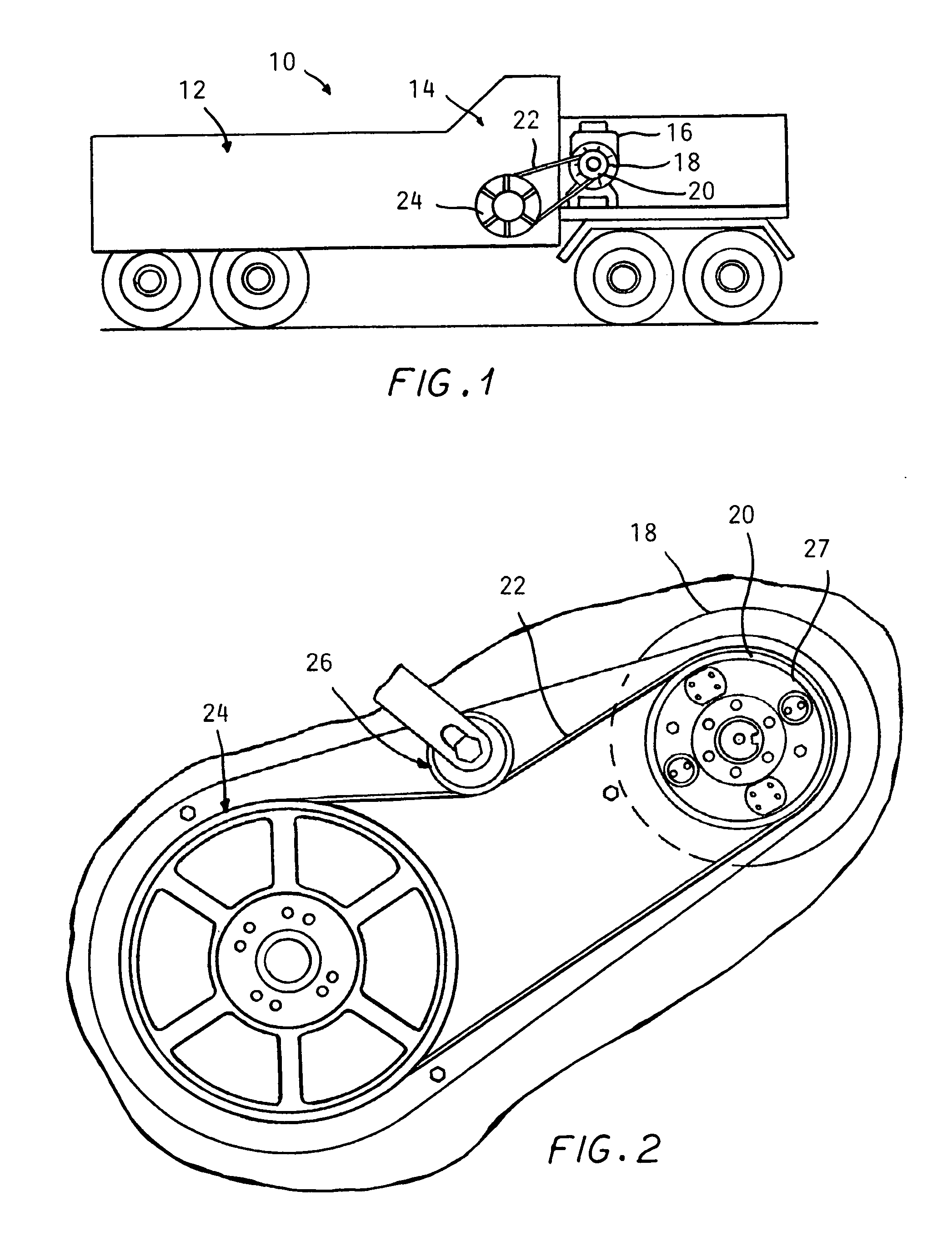
[0016]Referring to the drawings, FIG. 1 shows a simplified representation of a horizontal grinder 10 of the type described, in which wood material is fed onto a conveyor from a loading end 12 which drives the material to a hammer mill 14. Such equipment is well known in the art and accordingly will not be described in further detail.

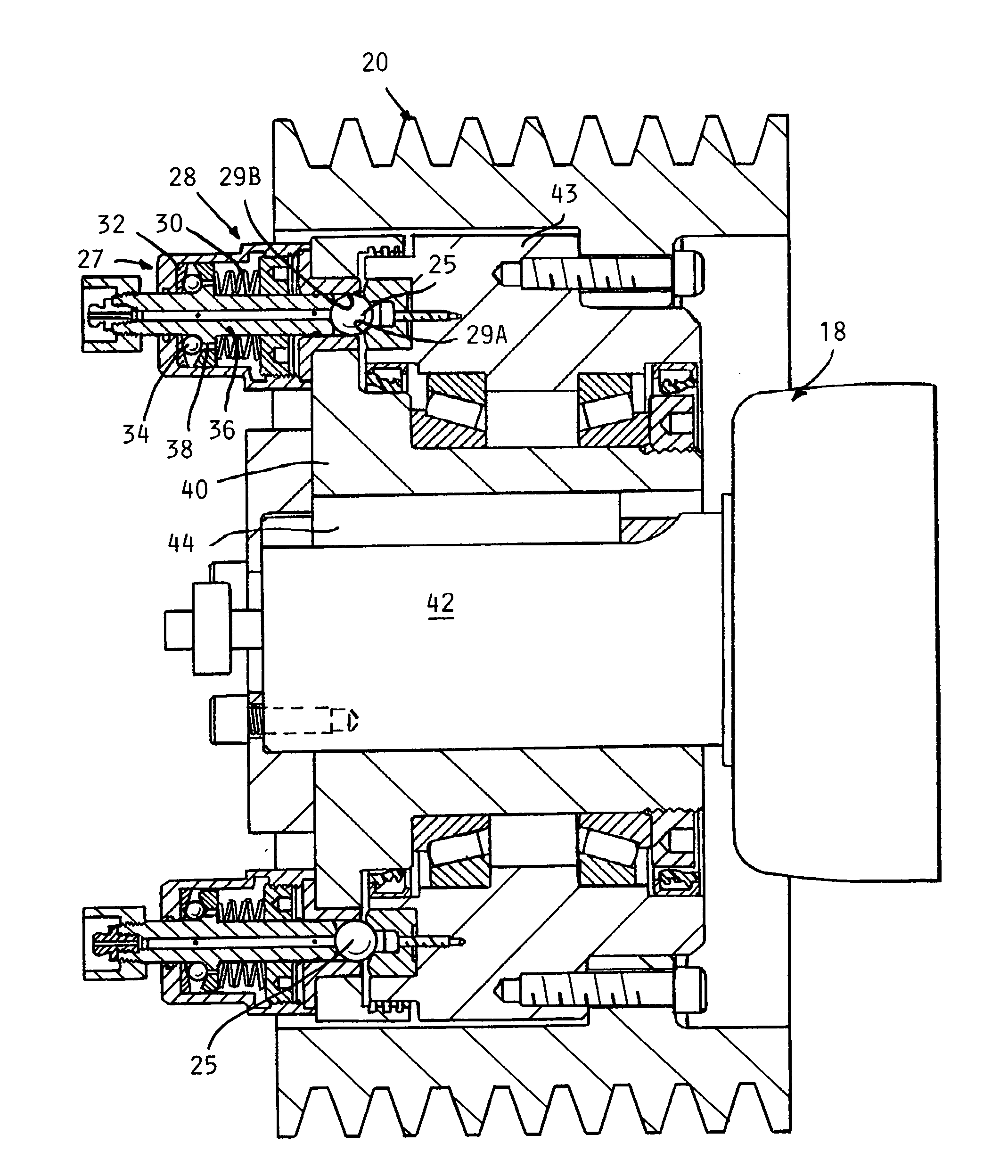
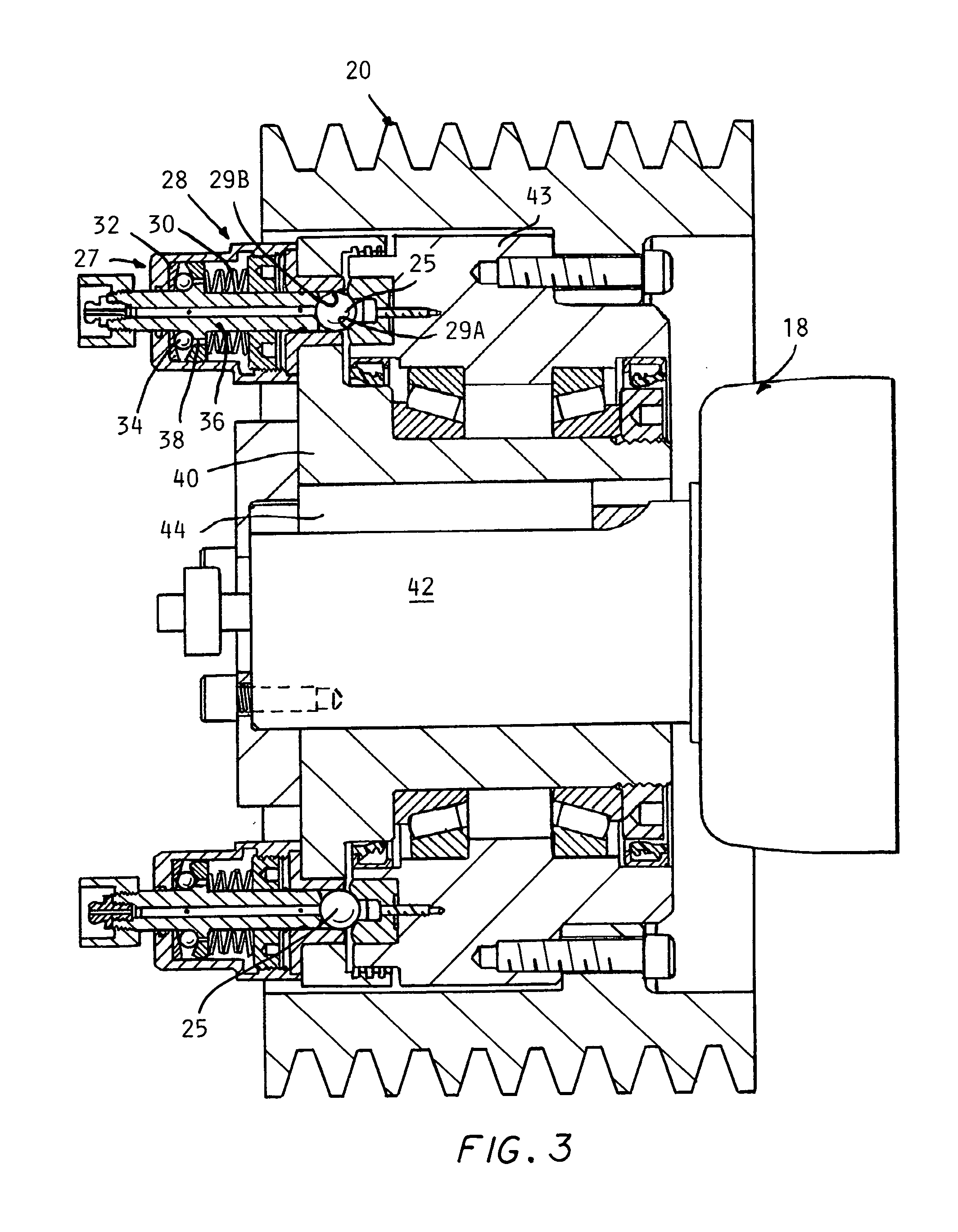
[0017]A diesel engine 16 drives friction clutch 18, having an output shaft 42 (FIG. 3) which is connected to a drive sheave 20 which is connected via a drive belt 22 to rotate a larger diameter driven sheave 24, achieving a reduction and incr...


PUM


Abstract

A compact low capacity torque limiter is installed in a drive sheave of a belt drive connecting an engine to the hammer mill of a horizontal grinder.

Description

CROSS REFERENCE TO RELATED APPLICATIONS[0001]This application claims the benefit of U.S. provisional application No. 61 / 207,539 filed Feb. 13, 2009.BACKGROUND OF THE INVENTION[0002]This invention concerns torque limiter applications and particularly in horizontal grinders used in community wood. Such grinders feed refuse wood material with conveyor to enter a hammer mill which carries out the reduction of heavy wood scrap. Such equipment involves powerful diesel engines in the order of 1000 hp.[0003]Such mills occasionally jam, potentially bringing all of the drive components to a stop. Such large engines cannot be allowed to stop in this event as considerable damage can be done to the engine components in such an event.[0004]For this reason torque limiters have been employed to automatically release and disconnect the driving components from the mill in the event of a jam causing torque increases beyond a preset limit.[0005]In U.S. Pat. No. 6,474,579 such a torque limiter installat...

Claims


Application Information

Patent Timeline
Patent Type & Authority Applications(United States)
IPC IPC(8): F16H7/00F16D43/204
CPCF16D7/08F16H55/36F16D43/206
Inventor LONG, JR., THOMAS F.
Owner BRUNEL GMBH
Why Eureka
Try Eureka