
Wind turbine with monitoring sensors

Active Publication Date: 2010-08-19
PRUTECHNIK DIETER BUSCH AG
View PDF13 Cites 23 Cited by
  • Summary
  • Abstract
  • Description
  • Claims
  • Application Information

AI Technical Summary

Benefits of technology

[0018]This object is achieved by providing each rotor blade of a wind turbine with at least one inclinometer arrangement that has at least two axes, in combination with an evaluating unit in communication with the at least one inclinometer arrangement. The evaluation unit determines the bending and / or twisting of the blade relative to the longitudinal axis of the blade, thus making possible a reliable evaluation of the state relative to the operationally induced deformations of the rotor blades. It is especially advantageous that by means of inclinometers, reference to the direction of rotation or to the geocenter is produced, i.e., an absolute frame of reference is predetermined by which the accuracy of the measurement of the deformation of the rotor blade can be achieved. Furthermore, the pitch adjustment of the rotor blades can also be monitored by means of the inclinometer arrangement.

Problems solved by technology

Wind turbines are basically subject to vibration, in particular because of the rotor being out of balance.
The imbalances that occur are due primarily to either mass imbalances or aerodynamic imbalances.
Mass imbalances may arise because of unequal rotor blade masses or unequal mass distributions in the individual rotor blade, hub imbalances, eccentricities of the complete rotor, icing on the rotor blades, or water penetration inside the rotor blades.
Aerodynamic imbalances may arise because of blade angle errors, unequal rotor blade profile shapes, rotor blade damage, oblique inflow of the rotor, as well as site-based excitations from outside, (e.g., by tower resonance and the fact that the wind speed generally depends on the height above ground such that one and the same rotor blade is exposed to different aerodynamic forces, depending on whether it is just below or above).
Such imbalances result in a reduced service life of the wind turbine.
The monitoring of the state of the rotor blades by means of strain gauges is problematic in as much as strain gauges are difficult to install and are relatively short-lived.

Method used


Image

  • Wind turbine with monitoring sensors
  • Wind turbine with monitoring sensors
  • Wind turbine with monitoring sensors

Examples


Embodiment Construction

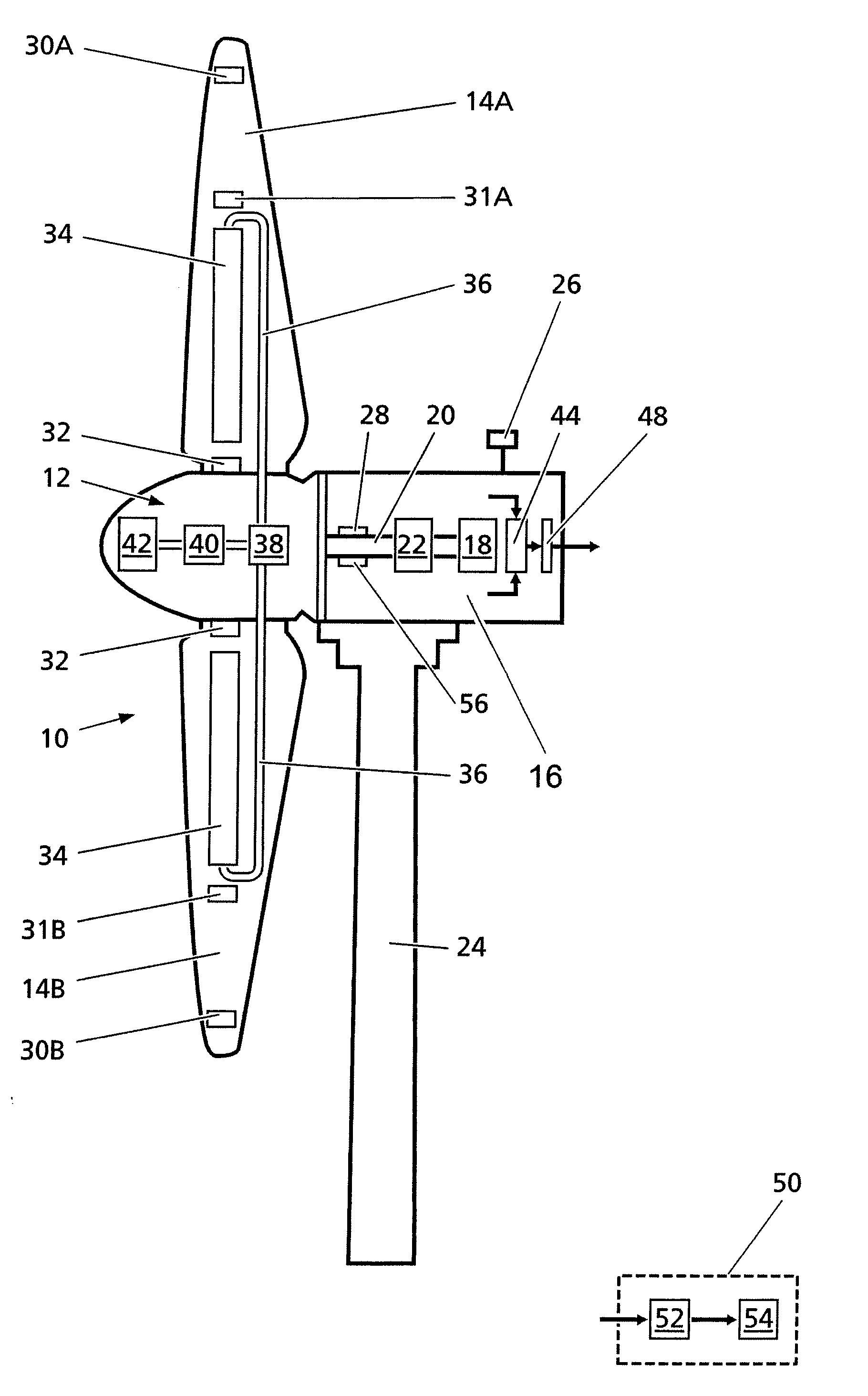
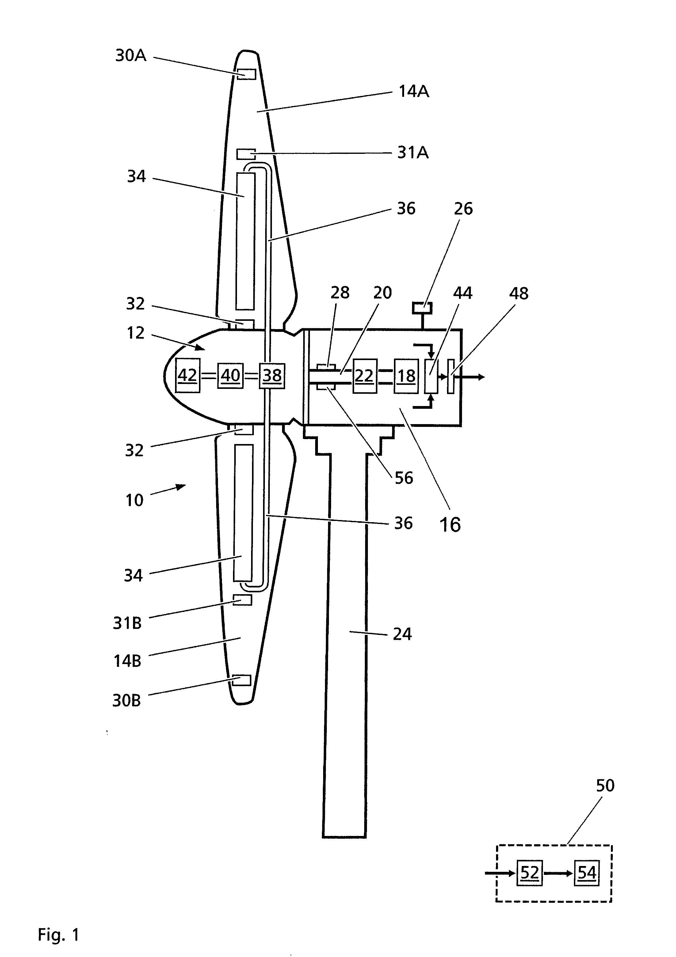
[0023]FIG. 1 shows a diagrammatic example of a wind turbine according to the invention. In this case, a rotor 10 is provided with a hub 12 for three rotor blades (of which only two rotor blades 14A, 14B are shown in FIG. 1). The rotor 10 is mounted in horizontal orientation in a nacelle 16, which accommodates a generator 18 that is driven by the rotor shaft 20 via a drive 22. The nacelle 16 is mounted on a tower 24 to rotate around a vertical axis. The housing also has a sensor 26 for the wind speed and the wind direction. In addition, a sensor 28 is provided for the detection of the speed of the rotor 10.

[0024]In each rotor blade 14A, 14B, at least one inclinometer arrangement that has at least two axes is provided (in the example, two inclinometer arrangements 30A, 31A or 30B, 31B that are offset on each rotor blade in the longitudinal direction of the blade are shown). The inclinometer arrangements are provided in order to determine the bending and / or twisting of the blade relati...


PUM


Abstract

A vibration-resistant wind turbine and process for operation is provided. The wind turbine has a rotor with at least two blades, each of which includes an inclinometer arrangement with at least two axes, and an evaluating unit. The evaluating unit determines the bending and / or twisting of the blade relative to the longitudinal axis of the blade on the basis of signals from the inclinometer arrangement for each blade during operation. Each rotor blade further has at least one liquid tank which is capable of receiving or transferring liquid from or to a liquid reservoir via a transfer mechanism in response to the determined bending and / or twisting of the rotor blades to reduce vibration caused by imbalances, thereby extending the service life of the wind turbine.

Description

BACKGROUND OF THE INVENTION[0001]1. Field of the Invention[0002]This invention generally relates to a vibration-resistant wind turbine, and is specifically concerned with a wind turbine having a rotor with at least two blades, each of which includes an inclinometer arrangement with at least two axes, and a process of operation.[0003]2. Description of Related Art[0004]Wind turbines typically comprise a rotor—with a hub and three rotor blades—that is mounted in horizontal orientation in an engine housing. The housing accommodates a rotor-driven generator and is mounted to rotate on a tower. In general, the rotor blades are mounted in an adjustable manner on the rotor hub to control the angle of attack of each individual rotor blade separately. In current research, it is even considered to also adjust parts of the rotor blade separately. By such an adjustment of the angle of attack (also referred to as pitch angle), the speed of the rotor can be regulated.[0005]Wind turbines are basica...

Claims


Application Information

Patent Timeline
IPC IPC(8): F03B3/12
CPCF03D1/008Y02E10/723F03D7/0224F03D7/024F03D7/0292F03D7/042F03D9/001F03D11/0091F05B2260/60F05B2260/74F05B2260/80F05B2260/96F05B2270/821Y02E10/721Y02E10/722F03D1/065F03D17/00F03D9/28F03D13/35F03D1/0675F03D9/17F03D9/25Y02E10/72Y02E60/16Y02E70/30
Inventor BECKER, EDWINKENZLER, MARCELLOESL, JOHANN
Owner PRUTECHNIK DIETER BUSCH AG
Learn More