System for quantitative radiographic imaging

a radiographic imaging and quantitative technology, applied in the field of radiographic examination equipment, can solve the problems of increasing the risk of fracture or similar bone related injury, poor spatial resolution, and limited current rectilinear scanning approach, and achieve the effect of reducing or eliminating scattered radiation

Inactive Publication Date: 2010-08-19
KARELLAS ANDREW
View PDF12 Cites 14 Cited by
  • Summary
  • Abstract
  • Description
  • Claims
  • Application Information

AI Technical Summary

Benefits of technology

[0012]The CCD acquires “frames” of information by counting the number of gamma-ray events over a selected period of time. Each frame, or a sequence of frames that have been added or summed to provide an image, can be filtered using pulse height analysis techniques to substantially reduce or eliminate scattered radiation. Pulse height analysis can also be utilized to discriminate between signals having different energy levels that contain diagnostically significant information. The system's discrimination and energy measuring capabilities render it suitable for diverse applications.

Problems solved by technology

Such a condition is common in elderly women and greatly increases the risk of fracture or similar bone related injury.
The current rectilinear scanning approach is generally limited by its long scanning time and its lack of good spatial resolution.
The poor spatial resolution results in an inability to provide an image displaying high anatomical detail and which will permit accurate determination of the area in the scan occupied by bone.

Method used


Image

  • System for quantitative radiographic imaging
  • System for quantitative radiographic imaging
  • System for quantitative radiographic imaging

Examples


Embodiment Construction

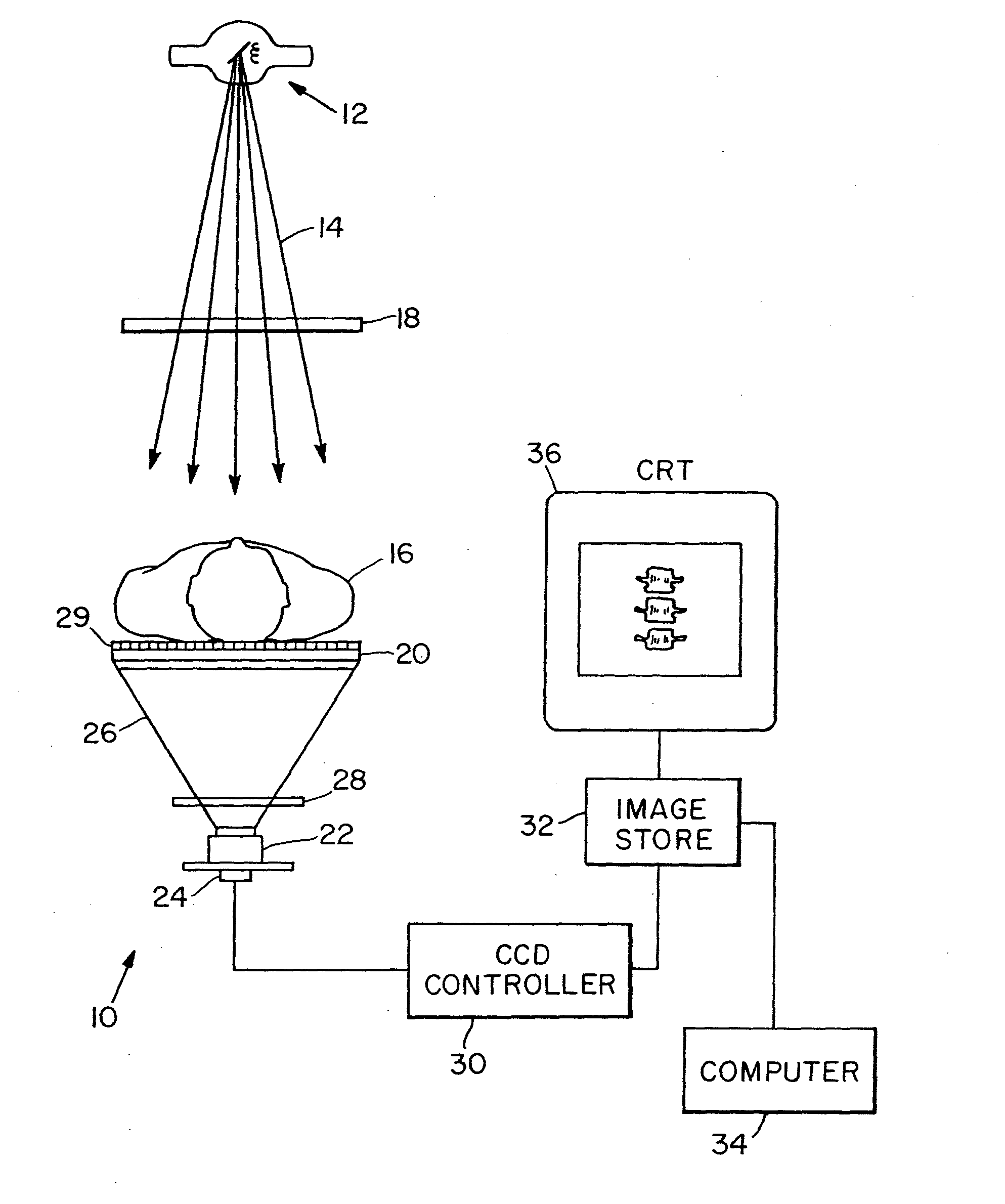
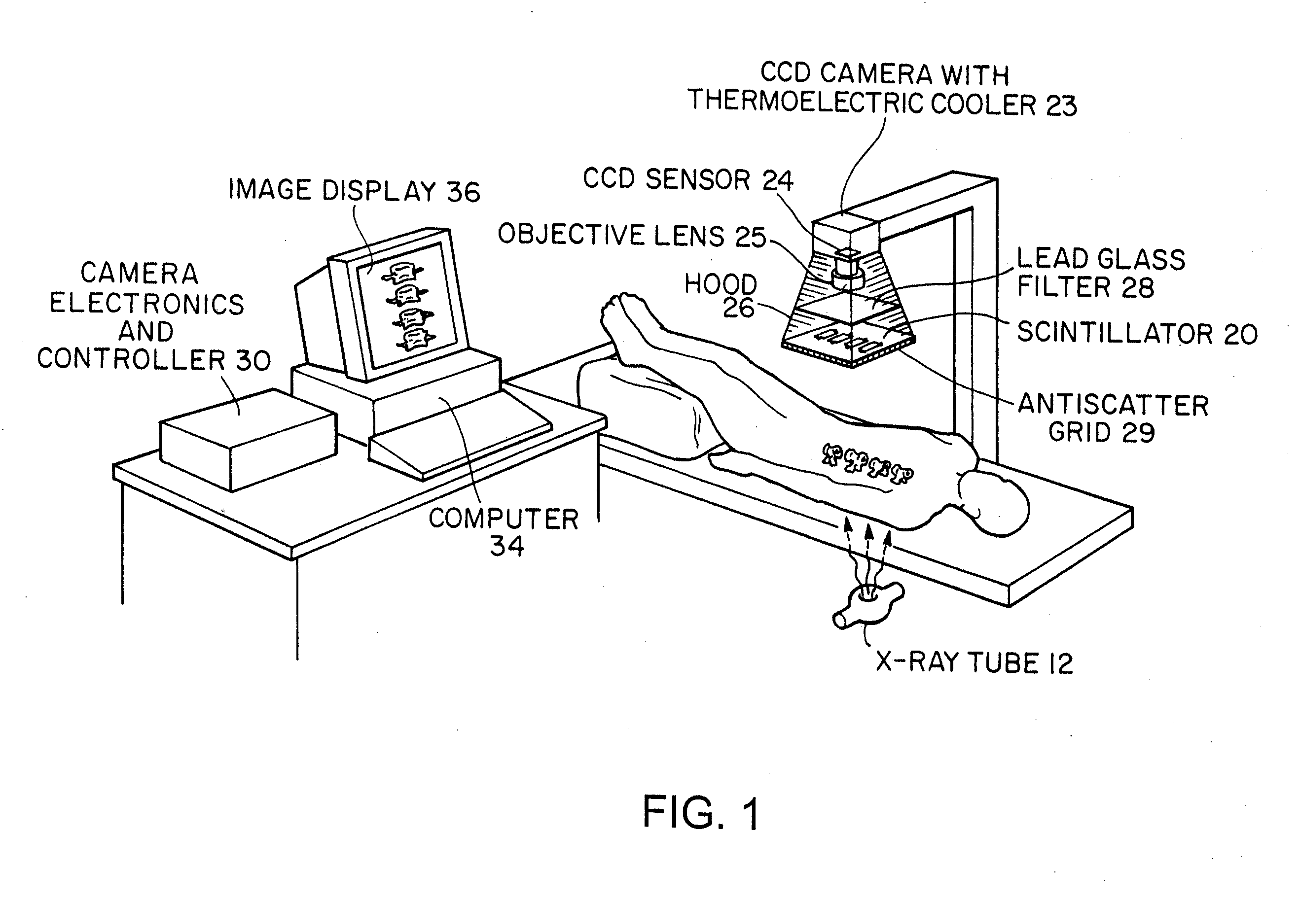
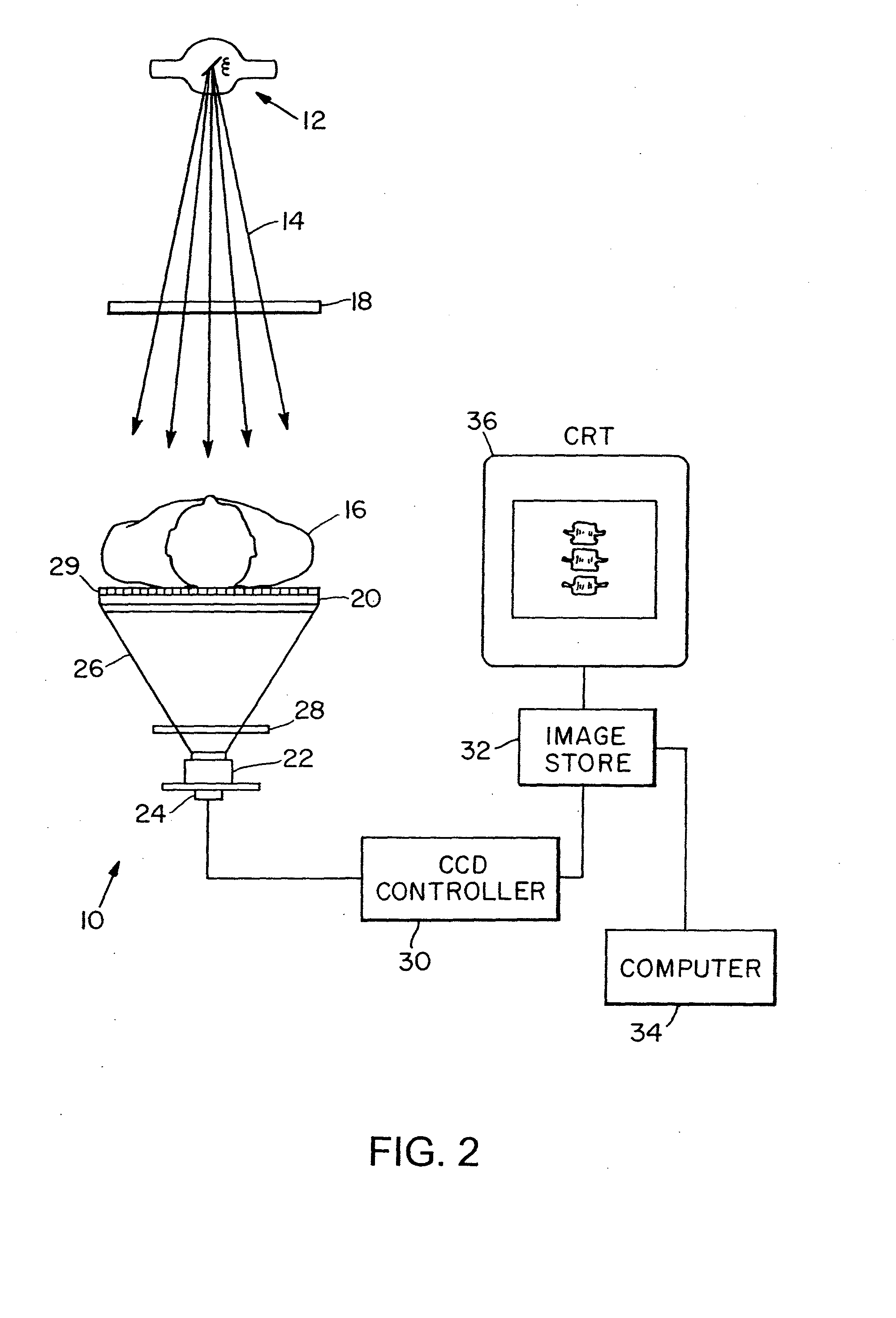
[0045]In FIG. 1 a preferred embodiment of the invention for performing bone densitometry studies uses a detector 10 and either an x-ray tube 12 or a radionuclide radiation source such as Gadolinium-153. The detector 10 comprises a scintillating plate 20 which is optically coupled to a two-dimensional charge-coupled device 24 (CCD). The CCD is a two dimensional array of detectors integrated into a single compact electronic chip. The optical coupling between the scintillating plate 20 and the CCD 24 is accomplished by an optical grade lens 25. Such a lens should have a low f-number (0.6-1.8) for adequate light collection from the screen. The collection efficiency (E) of light from the scintillating plate emitted in the direction of the CCD can be computed by the equation:

E=tm24f2(m+1)2

where:

[0046]t: Transmission factor of light through the lens

[0047]m: magnification from the Scintillating plate to the CCD

[0048]f: f-number of the lens

[0049]In an alternate approach, the optical coupling...


PUM


Abstract

A system for spectroscopic imaging of bodily tissue in which a scintillation screen and a charged coupled device (CCD) are used to accurately image selected tissue. An x-ray source generates x-rays which pass through a region of a subject's body, forming an x-ray image which reaches the scintillation screen. The scintillation screen reradiates a apatial intensity pattern corresponding to the image, the pattern being detected by a CCD sensor. The image is digitized by the sensor and processed by a controller before being stored as an electronic image. Each image is directed onto an associated respective CCD or amorphous silicon detector to generate individual electronic representations of the separate images.

Description

CROSS REFERENCES TO RELATED APPLICATIONS[0001]This application is a continuation of U.S. patent application Ser. No. 10 / 212,300 filed Aug. 5, 2002, which is a continuation of U.S. patent application Ser. No. 09 / 389,760 filed Sep. 2, 1999 which is a continuation of U.S. patent application Ser. No. 08 / 469,895 filed Jun. 6, 1995, now U.S. Pat. No. 6,031,892 which is a continuation-in-part of U.S. patent application Ser. No. 08 / 438,800 filed May 11, 1995. The entire contents of the above applications are incorporated herein by reference in entirety.BACKGROUND OF THE INVENTION[0002]In recent years the use of radiological examining equipment to make measurements of bone density in patients has continually increased. In particular, the use of such equipment in diagnosing and analyzing osteoporosis has become prevalent in the medical community. Osteoporosis is characterized by the gradual loss of bone mineral content or atrophy of skeletal tissue, resulting in a corresponding overall decrea...

Claims


Application Information

Patent Timeline
Patent Type & Authority Applications(United States)
IPC IPC(8): H05G1/64A61B5/00A61B6/00A61B6/03A61B6/14G21K1/10G21K3/00G21K4/00H04N5/225H04N5/32
CPCA61B5/0091A61B6/4258A61B6/145A61B6/4035A61B6/405A61B6/4233A61B6/4241A61B6/4488A61B6/502A61B6/505G21K1/10G21K4/00H04N5/2253H04N5/32A61B6/4291A61B6/4423A61B6/508A61B6/06H04N23/54
Inventor KARELLAS, ANDREW
Owner KARELLAS ANDREW
Why Eureka
Try Eureka