Method and Apparatus for Configuring a Wireless Sensor
- Summary
- Abstract
- Description
- Claims
- Application Information
AI Technical Summary
Benefits of technology
Problems solved by technology
Method used
Image
Examples
first embodiment
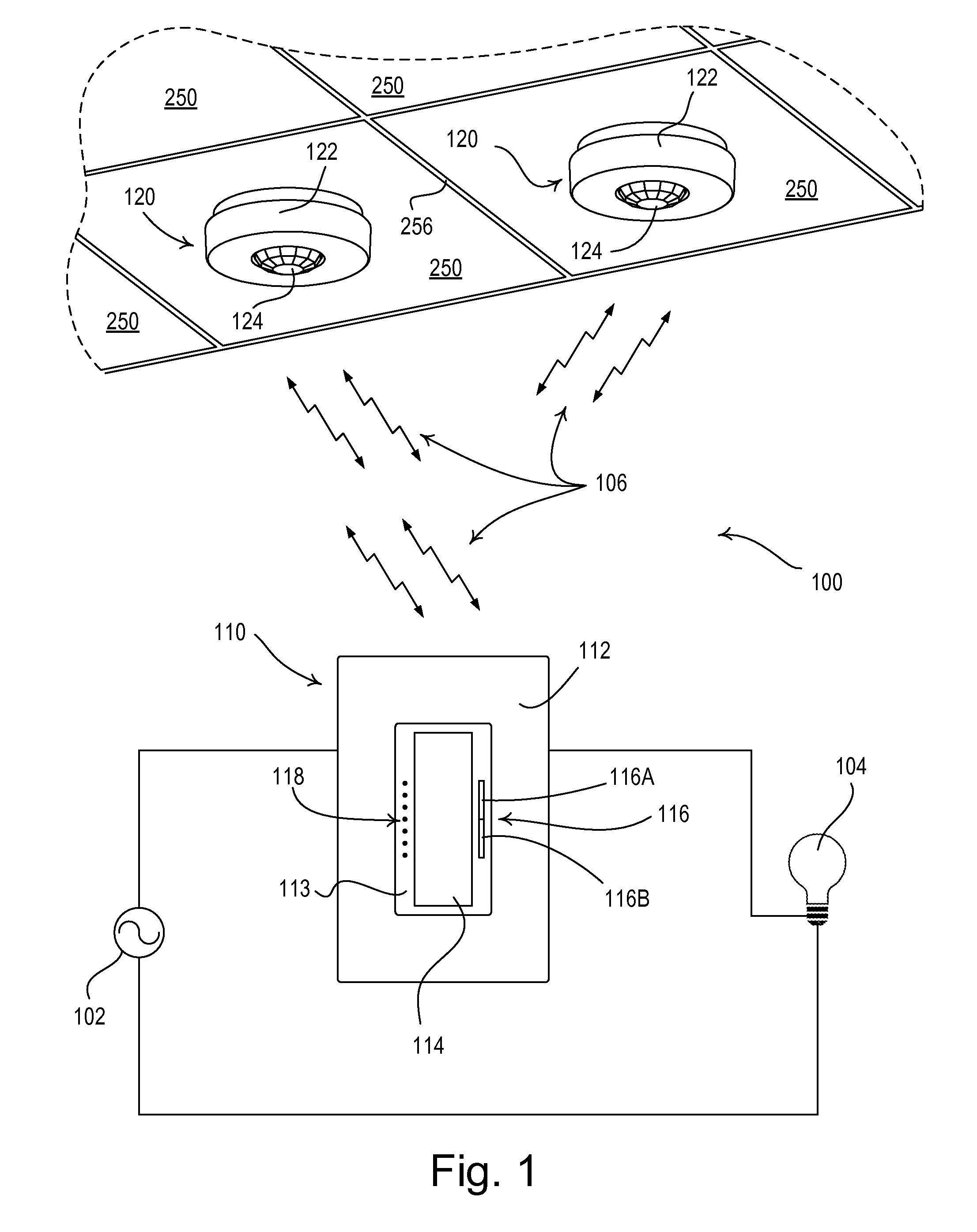
[0034]FIG. 1 is a simple diagram of a radio-frequency (RF) lighting control system 100 comprising a dimmer switch 110 and two remote occupancy sensors 120 (e.g., passive infrared sensors) according to the present invention. The dimmer switch 110 is adapted to be coupled in series electrical connection between an AC power source 102 and a lighting load 104 for controlling the amount of power delivered to the lighting load. The dimmer switch 110 may be adapted to be wall-mounted in a standard electrical wallbox, and comprises a faceplate 112 and a bezel 113 received in an opening of the faceplate. The dimmer switch 110 further comprises a control actuator 114, i.e., a button, and an intensity adjustment actuator 116. Actuations of the control actuator 114 toggle, i.e., turn off and on, the lighting load 104. Actuations of an upper portion 116A or a lower portion 116B of the intensity adjustment actuator 116 respectively increase or decrease the amount of power delivered to the lightin...
second embodiment
[0063]FIG. 15 is a diagram of an RF lighting control system 800 having an occupancy sensor 820 according to the present invention. The occupancy sensor 820 is releasably attached to the metal grid structure 256 that holds up the drop ceiling panels 250. FIG. 16 is a rear perspective view of the occupancy sensor 820. The occupancy sensor 820 comprises two magnets 850 attached (e.g., glued) to the rear surface 236 of the mounting plate 216, so that the occupancy sensor may be magnetically attached (and thus releasably attached) to the grid structure 256. The magnets 850 may comprise, for example, rare earth Neodymium-Iron-Boron magnets, each having a diameter of approximately 0.25 inch and a height of approximately 0.125 inch. The magnets 850 are arranged along a line that runs through the center of the circle formed by the rear surface 236 of the mounting plate 216, such that approximately one-half of the occupancy sensor 820 is located on each side of the grid structure 256 to which...
PUM
| Property | Measurement | Unit |
|---|---|---|
| Length | aaaaa | aaaaa |
| Diameter | aaaaa | aaaaa |
| Diameter | aaaaa | aaaaa |
Abstract
Description
Claims
Application Information
 - R&D
- Intellectual Property
- Life Sciences
- Materials
- Tech Scout
- Unparalleled Data Quality
- Higher Quality Content
- 60% Fewer Hallucinations
Browse by: Latest US Patents, China's latest patents, Technical Efficacy Thesaurus, Application Domain, Technology Topic, Popular Technical Reports.
© 2025 PatSnap. All rights reserved.Legal|Privacy policy|Modern Slavery Act Transparency Statement|Sitemap|About US| Contact US: help@patsnap.com


