
Spherical rotary piezoelectric motor

a piezoelectric motor and rotary technology, applied in piezoelectric/electrostrictive/magnetostrictive devices, piezoelectric/electrostriction/magnetostriction machines, electrical apparatus, etc., can solve the problems of complicated implementation of the above-described piezoelectric motor and achieve the effect of better conducting

Inactive Publication Date: 2010-08-19
CHUNG YUAN CHRISTIAN UNIVERSITY
View PDF16 Cites 19 Cited by
  • Summary
  • Abstract
  • Description
  • Claims
  • Application Information

AI Technical Summary

Benefits of technology

[0010]The plurality of piezoelectric actuators is arranged at least in a line along the outer surface of the hemispherical stator such that the spherical rotor can rotate with at least one degree of freedom. To achieve two degrees of freedom, the piezoelectric actuators are arranged in an orthogonal cross shape on the outer surface of the hemispherical stator. Furthermore, when the piezoelectric actuators are additionally arranged in a circle along a hemispherical opening of the hemispherical stator, the spherical rotor can rotate with three degrees of freedom. Therefore, the present invention can achieve various multiple degrees of freedom through various arrangements of the piezoelectric actuators on the surface of the hemispherical stator.
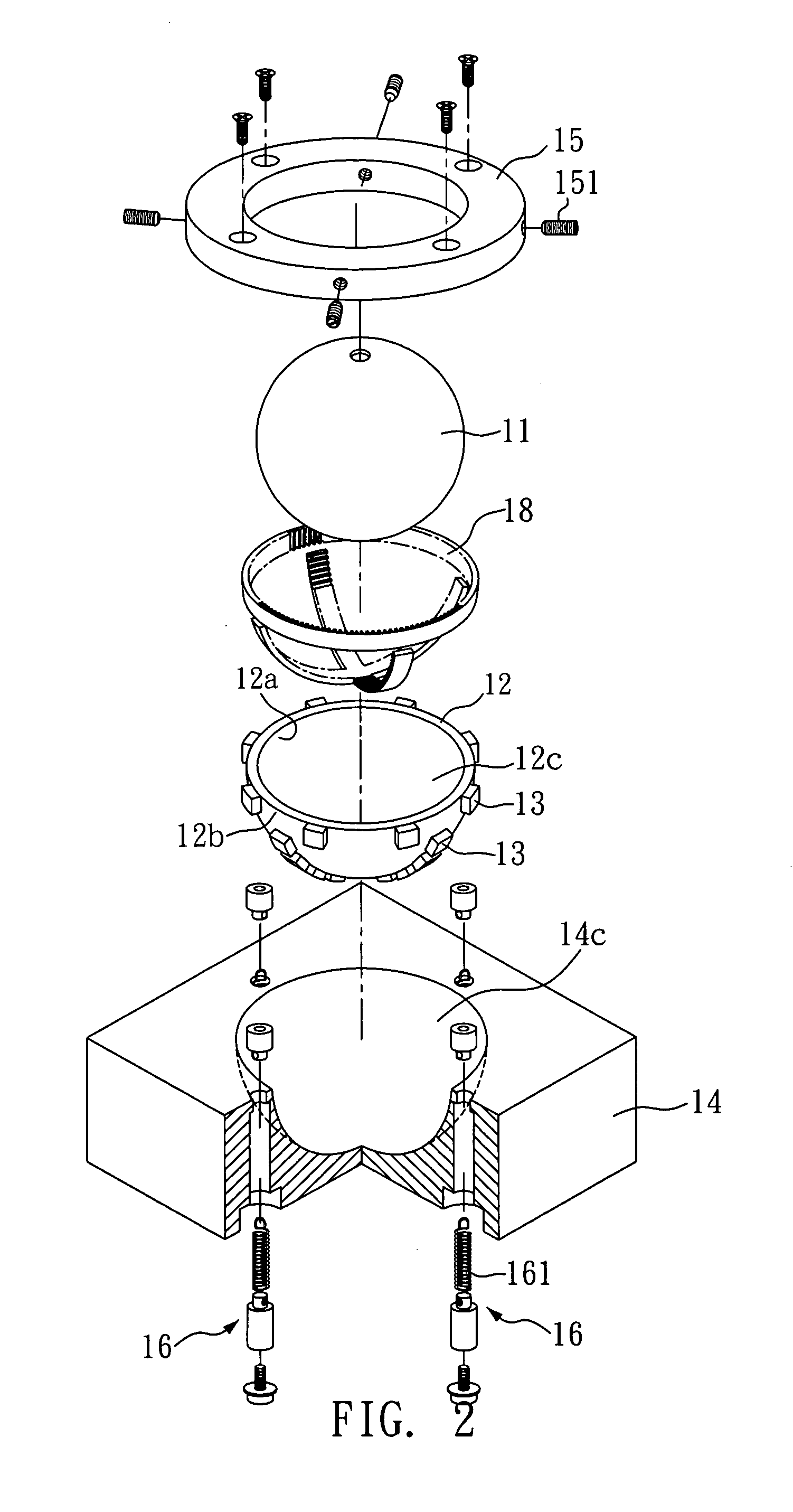
[0013]The spherical rotary piezoelectric motor in the present invention further comprises a base and a retaining ring, and the base includes a container portion corresponding to the hemispherical stator, wherein the retaining ring and the base are fixed by a plurality of elastic fixing members so as to have the spherical rotor, the hemispherical stator and the plurality of piezoelectric actuators disposed between the retaining ring and the base. In operations, the plurality of piezoelectric actuators drives the hemispherical stator to generate a traveling wave with an elliptical motion. Since the spherical rotor and the hemispherical stator are fixed between the retaining ring and the base, the traveling wave with the elliptical motion from the hemispherical stator can generate rotations with at least one degree of freedom.
[0015]Therefore, the present invention additionally provides a spherical rotary piezoelectric motor, which comprises a spherical rotor, a hemispherical stator and a plurality of piezoelectric actuators. What is different from the previous embodiment is that the plurality of piezoelectric actuators in this embodiment is arranged on the inner surface of the hemispherical stator respectively; that is, the plurality of piezoelectric actuators is disposed between the hemispherical stator and the spherical rotor. Similarly, the plurality of piezoelectric actuators can drive the hemispherical stator to generate a traveling wave with an elliptical motion, and the spherical rotor can rotate with at least one degree of freedom caused by the traveling wave with the elliptical motion.
[0017]In this embodiment, the plurality of piezoelectric actuators is disposed between the hemispherical stator and the spherical rotor. Preferably, the spherical rotary piezoelectric motor further comprises a contact layer, the contact layer substantially complies with the plurality of piezoelectric actuators along a line, and the contact layer is disposed between the plurality of piezoelectric actuators and the spherical rotor so as to amplify the traveling wave with the elliptical motion generated by the hemispherical stator and to precisely control the rotation of the spherical rotor. Preferably, one side of the contact layer contacting the spherical rotor is formed with gear teeth. For better conducting effect, the contact layer can be made of aluminum.

Problems solved by technology

Although the present piezoelectric motors provide various advantages and functions, the implementations of the above-described piezoelectric motors are still complicated; therefore, it is necessary to provide a simple rotary piezoelectric motor design which can achieve multi degrees of freedom.

Method used


Image

  • Spherical rotary piezoelectric motor
  • Spherical rotary piezoelectric motor
  • Spherical rotary piezoelectric motor

Examples


Embodiment Construction

[0029]The advantages and innovative features of the invention will become more apparent from the following detailed description when taken in conjunction with the accompanying drawings.

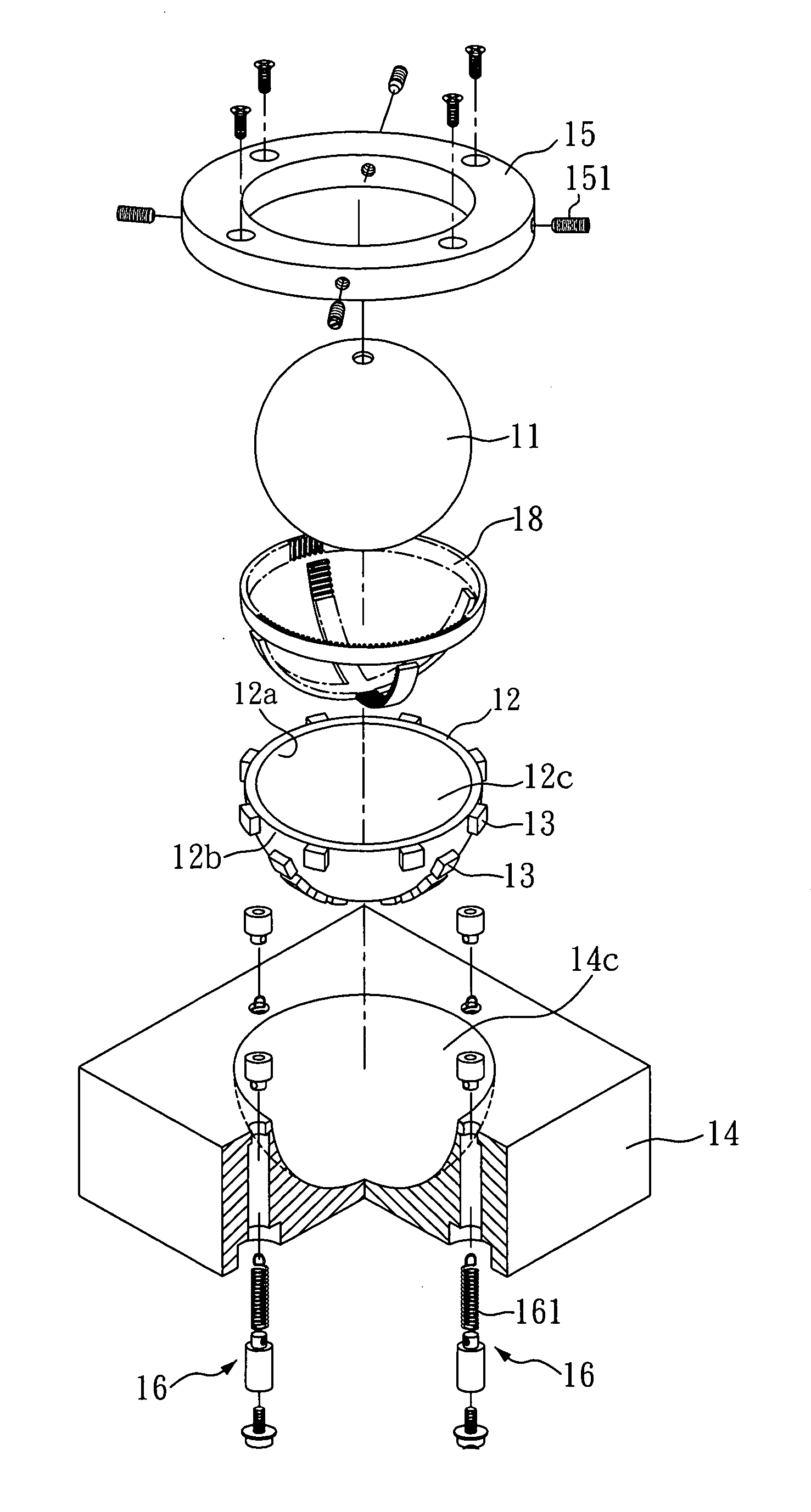
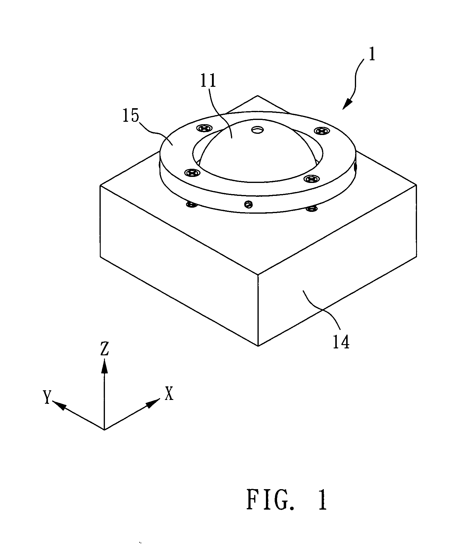
[0030]Please refer to the 3D view of FIG. 1 and the explosive view of FIG. 2 at the same time. The present invention provides a spherical rotary piezoelectric motor 1, which comprises a spherical rotor 11, a hemispherical stator 12, and a plurality of piezoelectric actuators 13.

[0031]The hemispherical stator 12 comprises an inner surface 12a and an outer surface 12b, the inner surface 12a forms a hemispherical hollow portion 12c, and the hemispherical hollow portion 12c substantially corresponds to the spherical rotor 11 for allowing the hemispherical hollow portion 12c to contain a portion of the spherical rotor 11 (such as one half of the spherical rotor 11 to facilitate rotation).

[0032]A plurality of piezoelectric actuators 13, which can be piezoelectric ceramic actuators, is disposed on the outer ...


PUM


Abstract

A spherical rotary piezoelectric motor comprises a spherical rotor, a hemispherical stator, and a plurality of piezoelectric actuators. The hemispherical stator comprises an inner surface and an outer surface, wherein the inner surface forms a hemispherical hollow portion which substantially corresponds to the spherical rotor so as to contain a portion of the spherical rotor. The plurality of piezoelectric actuators is arranged on the inner surface (or the outer surface) of the hemispherical stator respectively so as to drive the hemispherical stator. The hemispherical stator generates traveling waves with a resultant elliptical motion, so the spherical rotor can be rotated accordingly with at least one degree of freedom.

Description

BACKGROUND OF THE INVENTION[0001]1. Field of the Invention[0002]The present invention relates to a spherical rotary piezoelectric motor, and more particularly, to a multi degrees of freedom rotary traveling wave piezoelectric motor.[0003]2. Description of the Related Art[0004]Generally, piezoelectric motor has the advantages of small size, light weight, less noise, high thrust at low speed, high holding force, fast response, and no EMI problem, and so on. It has been widely used in many areas such as digital still camera, watch, automobile, robot, micro positioning system, medical device, aerospace, and micro machinery, etc.[0005]In order to achieve multi degrees of freedom by using piezoelectric motors, a few implementations have been proposed, such as (1) using piezoelectric actuators to support and to drive a spherical rotor so as to control the motions of the spherical rotor, this type of piezoelectric motor is used as the device of Scanning Electron Microscope (SEM); (2) using ...

Claims


Application Information

Patent Timeline
IPC IPC(8): H02N2/16
CPCH02N2/108H02N2/16
Inventor TING, YUNGLEE, YI-TA
Owner CHUNG YUAN CHRISTIAN UNIVERSITY
Learn More