
Adjustable Bar Guide

a bar guide and adjustable technology, applied in the direction of fastening means, construction fastening devices, building locks, etc., to achieve the effect of not being lost so easily

Inactive Publication Date: 2010-08-19
RAMSAUER DIETER
View PDF21 Cites 1 Cited by
  • Summary
  • Abstract
  • Description
  • Claims
  • Application Information

AI Technical Summary

Benefits of technology

[0008]It is the object of the invention to make possible a finer gradation of steps and to provide a novel configuration of the construction generally.
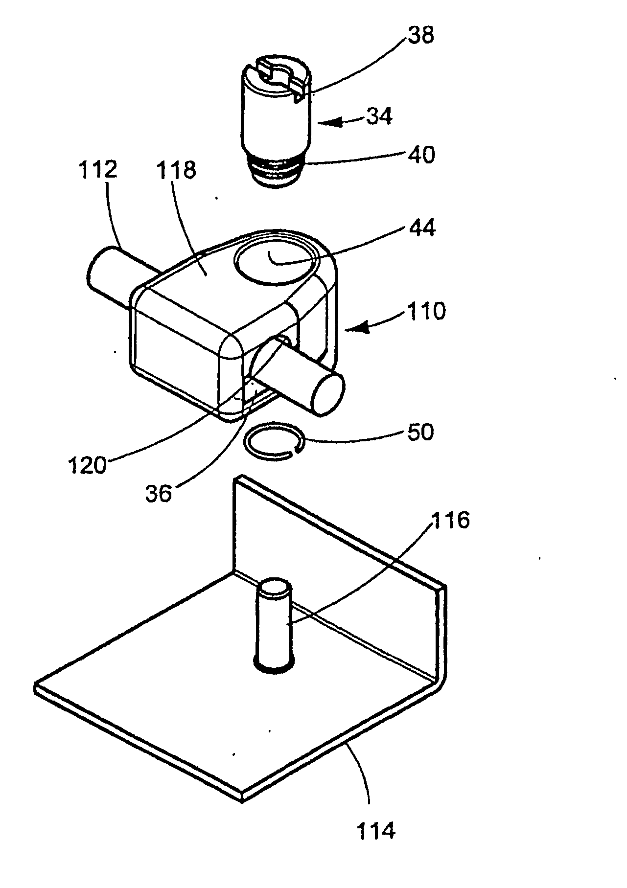
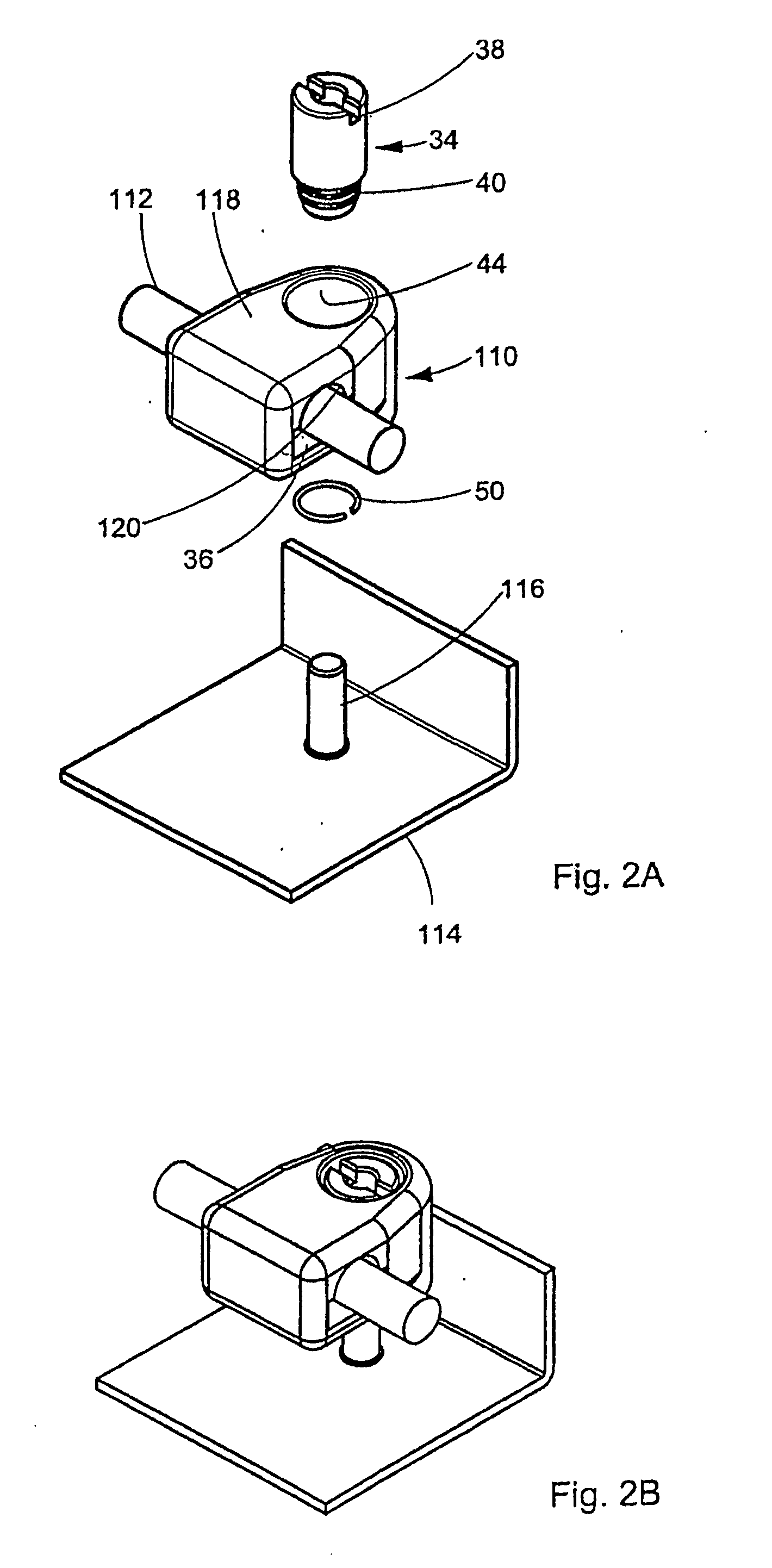
[0009]The above-stated object is met in that the carrier which is spot welded to the door leaf is a pin with a circumferential thread similar to that in the Utility Model Document, and an adjusting screw can be screwed, or is screwed, on this pin, and in that the guide element is a housing which encloses the adjusting screw and which has a guide channel forming the guide surface for the locking bar. The adjusting screw which can be screwed on the pin makes it possible to adjust the distance virtually continuously instead of by steps as in the prior art. Further, the shape of the novel bar guide is more attractive and there is no risk of injury to a user or installer due to protruding parts such as, e.g., the cotter pin according to FIG. 1A.
[0011]According to a further development, the shaft of the adjusting screw can be overdimensioned with respect to the area of the bore hole with the diameter reduction in such a way that the adjusting screw is self-retaining with respect to rotation in the bore hole. This obviates the need for other locking means which would otherwise be needed to prevent unwanted displacement of the screw.
[0012]A retaining ring can be provided near the end of the shaft and—together with the shoulder—prevents axial movement of the adjusting screw in the housing.
[0015]Therefore, the retaining ring and shoulder provide for limiting the axial movement and, therefore, the height of the bar guide above the plane of the door leaf. Accordingly, the distance of the alignment roller or alignment slide, for example, is also fixed so that the door closes smoothly.
[0017]The housing in the area of the spring support can have an annular projection or recess for receiving the end of the spring in a clamping manner so that the spring part cannot be lost so easily before it is mounted.

Problems solved by technology

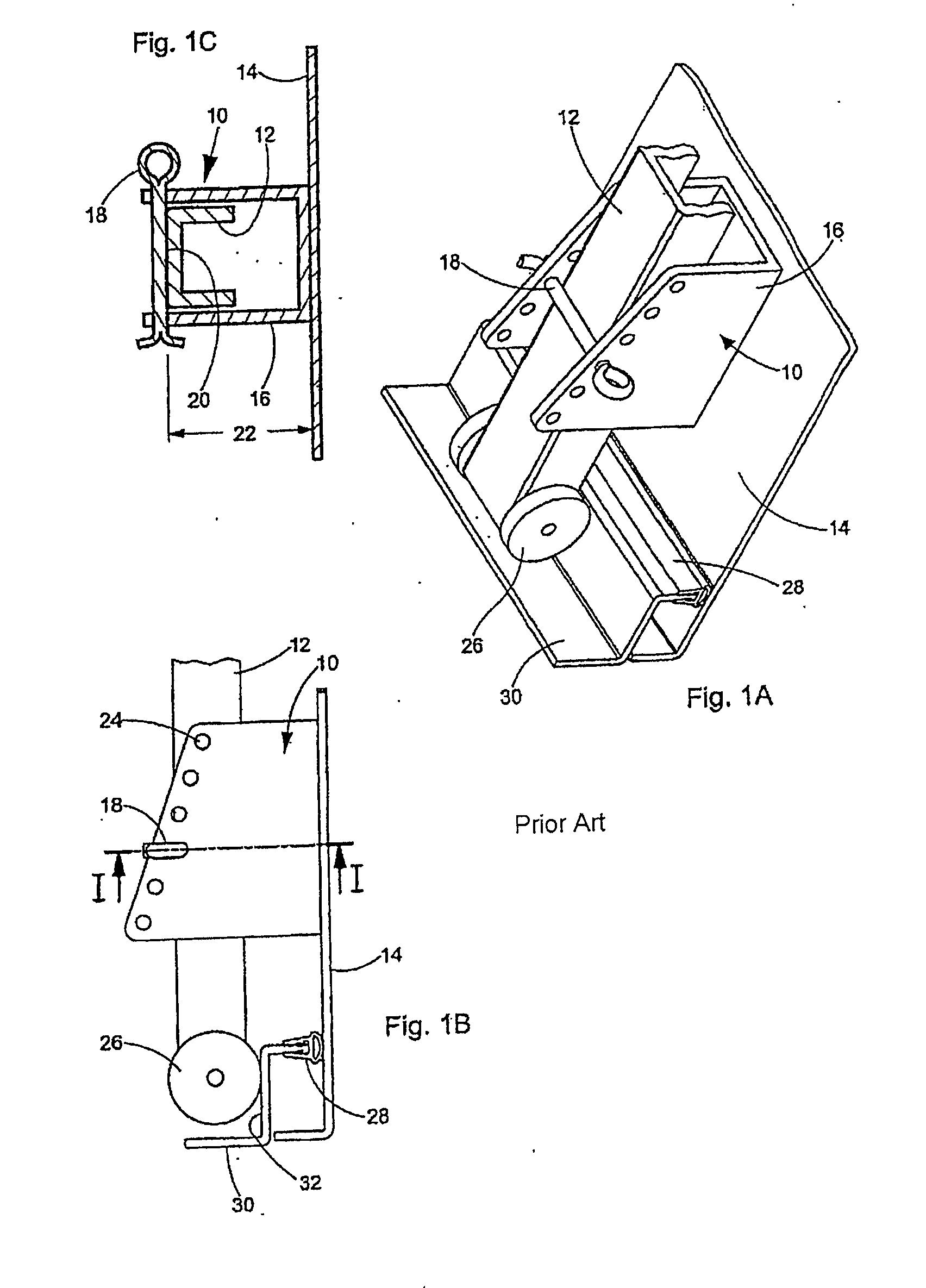
It is a drawback that the entire bar guide on the carrier (stud bolt with thread) must be turned in order to adjust the distance of the bar from the inside surface of the door leaf.

Method used


Image

  • Adjustable Bar Guide
  • Adjustable Bar Guide
  • Adjustable Bar Guide

Examples


Embodiment Construction

[0033]It is to be understood that the figures and descriptions of the present invention have been simplified to illustrate elements that are relevant for a clear understanding of the present invention, while eliminating, for purposes of clarity, many other elements which are conventional in this art. Those of ordinary skill in the art will recognize that other elements are desirable for implementing the present invention. However, because such elements are well known in the art, and because they do not facilitate a better understanding of the present invention, a discussion of such elements is not provided herein.

[0034]The present invention will now be described in detail on the basis of exemplary embodiments.

[0035]FIG. 1A shows a known guide for a locking bar 12 on a sheet metal cabinet door 14 comprising a carrier 16 which can be secured, e.g., spot welded, to the inside surface of the door leaf and which is constructed as a U-shaped part in this instance, and comprising a guide e...


PUM


Abstract

A bar guide for guiding locking bars on sheet metal cabinet doors, or the like, comprises a carrier which can be secured, e.g., spot welded, to the inside surface of the door leaf and a guide element which can be mounted on the carrier and which has a guide surface whose distance from the inside surface of the door leaf is adjustable. According to the invention, the carrier which is spot welded to the door leaf is a pin with a circumferential thread, and an adjusting screw or adjusting nut can be screwed, or is screwed, on this pin. The guide element is a housing which encloses the adjusting screw and which has a guide channel forming the guide surface for the locking bar.

Description

[0001]The present application claims priority from PCT Patent Application No. PCT / EP2008 / 001562 filed on Feb. 28, 2008, which claims priority from German Patent Application No. 20 2007 005 424.6 filed on Apr. 14, 2007, the disclosure of which is incorporated herein by reference in its entirety.BACKGROUND OF THE INVENTION[0002]1. Field of the Invention[0003]The invention is directed to a bar guide for guiding locking bars on sheet metal cabinet doors, or the like, comprising a carrier which can be secured, e.g., spot welded, to the inside surface of the door leaf and a guide element which can be mounted on the carrier and which has a guide surface which faces the door leaf, and the distance of the guide surface from the inside surface of the door leaf is adjustable.[0004]2. Description of Related Art[0005]A plastic bar guide having the features mentioned above is already known from EP 0 035 715 B1. It is a drawback that the entire bar guide on the carrier (stud bolt with thread) must...

Claims


Application Information

Patent Timeline
Patent Type & Authority Applications(United States)
IPC IPC(8): E05B15/02
CPCE05B15/1635E05C9/22E05B63/0056Y10T292/096Y10T292/1099Y10T292/20Y10T292/42Y10T292/45Y10T292/705
Inventor RAMSAUER, DIETER
Owner RAMSAUER DIETER
Learn More