
Reception apparatus and reception method

a technology of reception apparatus and reception method, which is applied in the direction of electrical apparatus, broadcast receiving circuit, transmission, etc., can solve problems such as error-prone search, and achieve the effect of reducing manufacturing costs

Inactive Publication Date: 2010-08-12
SONY CORP
View PDF15 Cites 3 Cited by
  • Summary
  • Abstract
  • Description
  • Claims
  • Application Information

AI Technical Summary

Benefits of technology

The patent text describes a problem with automatic searches for FM and AM broadcast stations, where errors can occur when searching for an AM broadcast station due to the presence of a digital radio broadcast spectrum. The invention proposes a solution by using a reception apparatus with a local oscillation section and a multipath detecting section to extract an amplitude change component from the received radio wave. The amplitude change component is detected when the intensity of the radio wave from an AM broadcast station and the frequency offset exceed a predetermined level. The invention prevents erroneous searches by not fixing the frequency of the local oscillation section when an amplitude change component is detected. This results in a reduction in manufacturing costs as no additional circuitry is required.

Problems solved by technology

While Patent Document 1 describes only a scheme of solving the problem that occurs during automatic search for an analog FM broadcast station, an erroneous search also occurs during automatic search for an AM broadcast station.
This is likely to cause an erroneous search particularly in the neighborhood of the frequency band.

Method used


Image

  • Reception apparatus and reception method
  • Reception apparatus and reception method
  • Reception apparatus and reception method

Examples


Embodiment Construction

[0024]An embodiment of the present invention will be described below with reference to the accompanying drawings. The description of the embodiment is given in the following order.

[0025]1. Fundamental Configuration of Receiving Apparatus

[0026]2. Example of Receiving Operation of Receiving Apparatus

[0027]3. Example of Receiving Process Executed by Receiving Apparatus

[0028]3-1. Example in case where a broadcast station with a high electric field intensity exists around the frequency to be searched

[0029]3-2. Example in case where a digital radio broadcast station exists around the frequency to be searched

[Fundamental Configuration of Receiving Apparatus]

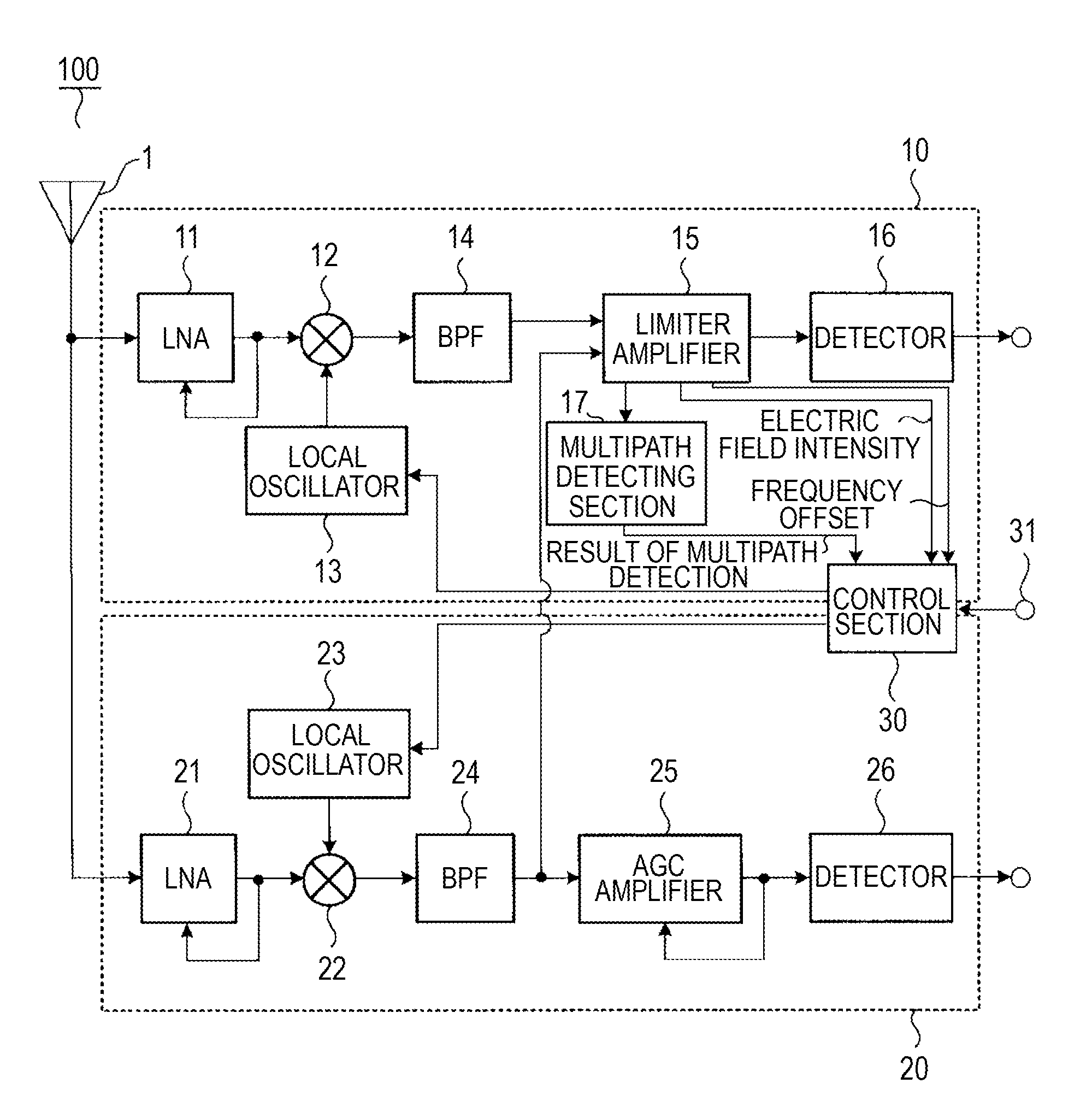
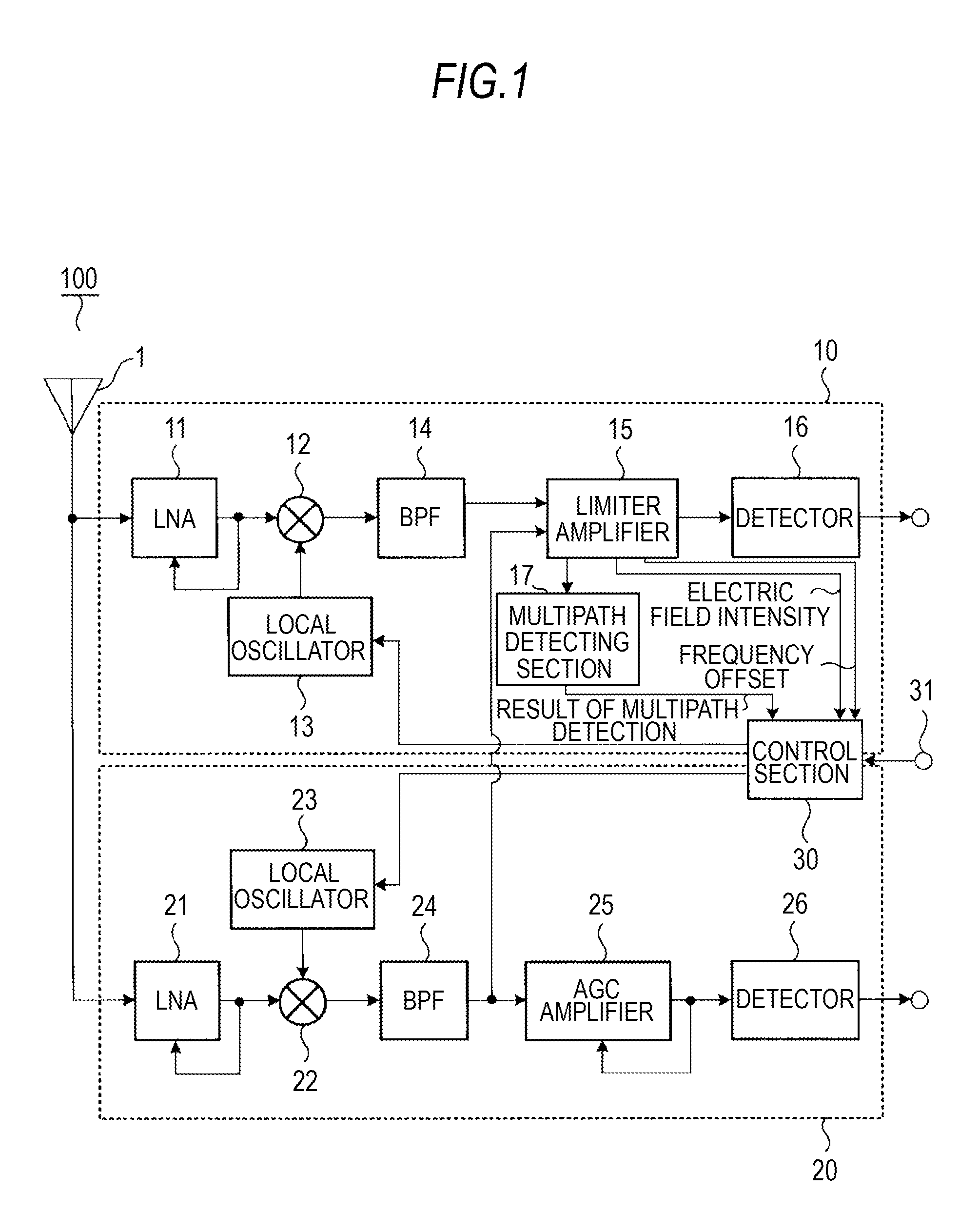
[0030]First, referring to FIG. 1, an example of the internal configuration of a reception apparatus 100 according to the embodiment will be described. The reception apparatus 100 capable of receiving an analog AM broadcast and an analog FM broadcast includes an antenna 1, which receives radio waves transmitted from both AM and FM broadc...


PUM


Abstract

A reception apparatus includes: a local oscillation section; first and second frequency mixing sections that mix received radio waves from AM and FM broadcast stations with an output signal from the local oscillation section to produce first and second intermediate frequency signals, respectively; an amplitude limiting section that limits an amplitude of the first or second intermediate frequency signal to a predetermined amplitude, and detects an intensity of the radio wave and a frequency offset from the signal; a multipath detecting section that extracts an amplitude change component in the signal amplitude-limited by the amplitude limiting section; and a control section that supplies a control signal for fixing the frequency to the local oscillation section when the intensity of the radio wave from the AM broadcast station and the frequency offset fulfill predetermined criteria, and when the amplitude change component is equal to or lower than a predetermined level.

Description

BACKGROUND OF THE INVENTION[0001]1. Field of the Invention[0002]The present invention relates to a reception apparatus and reception method, and, more particularly, to a reception apparatus capable of receiving an AM radio broadcast wave and an FM radio broadcast wave, and a reception method using the reception apparatus.[0003]2. Description of the Related Art[0004]In the past, many reception apparatuses which receive an AM radio broadcast wave and FM radio broadcast wave are provided with an automatic search function to automatically receive radio waves of a receivable broadcast station. Such a reception apparatus is provided with a plus key and minus key to instruct initiation of automatic search, so that at the timing when a user presses one of the keys, automatic search is initiated. Upon depression the plus key, for example, frequencies above the then tuned frequency are searched, and when a receivable broadcast station is detected, the broadcast wave thereof is received.[0005]...

Claims


Application Information

Patent Timeline
Patent Type & Authority Applications(United States)
IPC IPC(8): H04B1/18
CPCH04H40/18H04H2201/186H04H2201/183
Inventor KOMIYAMA, AKINORI
Owner SONY CORP
Learn More